2-2 T35 Transformer Protection System GE Multilin
2.1 INTRODUCTION 2 PRODUCT DESCRIPTION
2
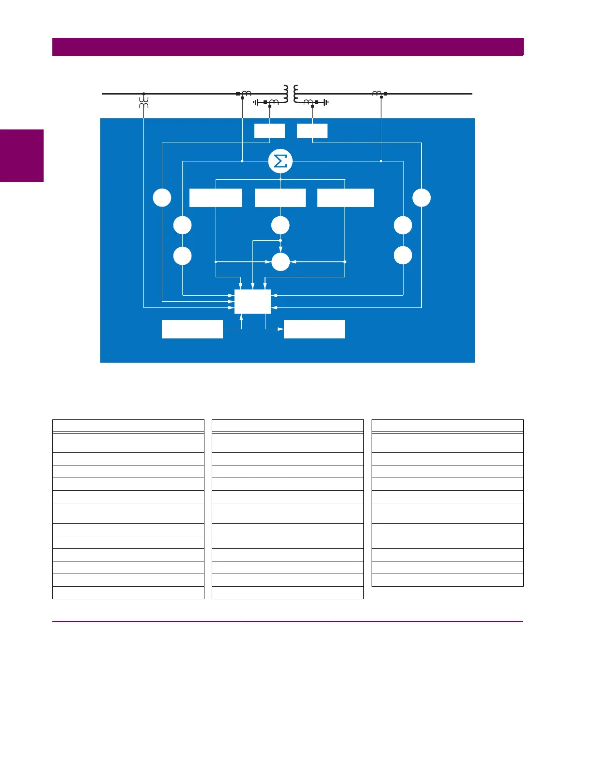
Figure 2–1: SINGLE LINE DIAGRAM
2.1.2 ORDERING
a) OVERVIEW
The T35 is available as a 19-inch rack horizontal mount or reduced-size (¾) vertical unit and consists of the following mod-
ules: power supply, CPU, CT/VT, contact input and output, transducer input and output, and inter-relay communications.
Each of these modules can be supplied in a number of configurations specified at the time of ordering. The information
required to completely specify the relay is provided in the following tables (see chapter 3 for full details of relay modules).
Table 2–2: OTHER DEVICE FUNCTIONS
FUNCTION FUNCTION FUNCTION
Breaker Arcing Current I
2
t Ethernet Global Data Protocol (optional) Time synchronization over IRIG-B or IEEE
1588
Breaker Control Event Recorder Time Synchronization over SNTP
Contact Inputs (up to 96) FlexElements (16) Transducer Inputs/Outputs
Contact Outputs (up to 64) FlexLogic Equations Trip Bus
Control Pushbuttons IEC 61850 Communications (optional) User Definable Displays
CT Failure Detector Metering: Current, Voltage, Power,
Power Factor, Frequency
User-Programmable Fault Reports
CyberSentry™ security Modbus Communications User Programmable LEDs
Data Logger Modbus User Map User Programmable Pushbuttons
Digital Counters (8) Non-Volatile Latches User Programmable Self-Tests
Direct Inputs/Outputs (32) Non-Volatile Selector Switch Virtual Inputs (64)
Disconnect Switches Oscillography Virtual Outputs (96)
DNP 3.0 or IEC 60870-5-104 Protocol Setting Groups (6)
828725A4.CDR
50/87
87T
Calculate
restraint current
Calculate
operate current
Metering
Transducer input
TM
FlexElement
Calculate 2nd and
5th harmonics
Measure
3I_0
Measure
3I_0
T35 Transformer Protection System
51P-2
51G
51P-1
51G
49-1
49-2

 Loading...


