9-10 T35 Transformer Protection System GE Multilin
9.2 DIFFERENTIAL CHARACTERISTIC TEST EXAMPLES 9 COMMISSIONING
9
9.2.4 TEST EXAMPLE 3
Yg/D30° TRANSFORMER WITH PHASE B TO C FAULT ON THE DELTA SIDE.
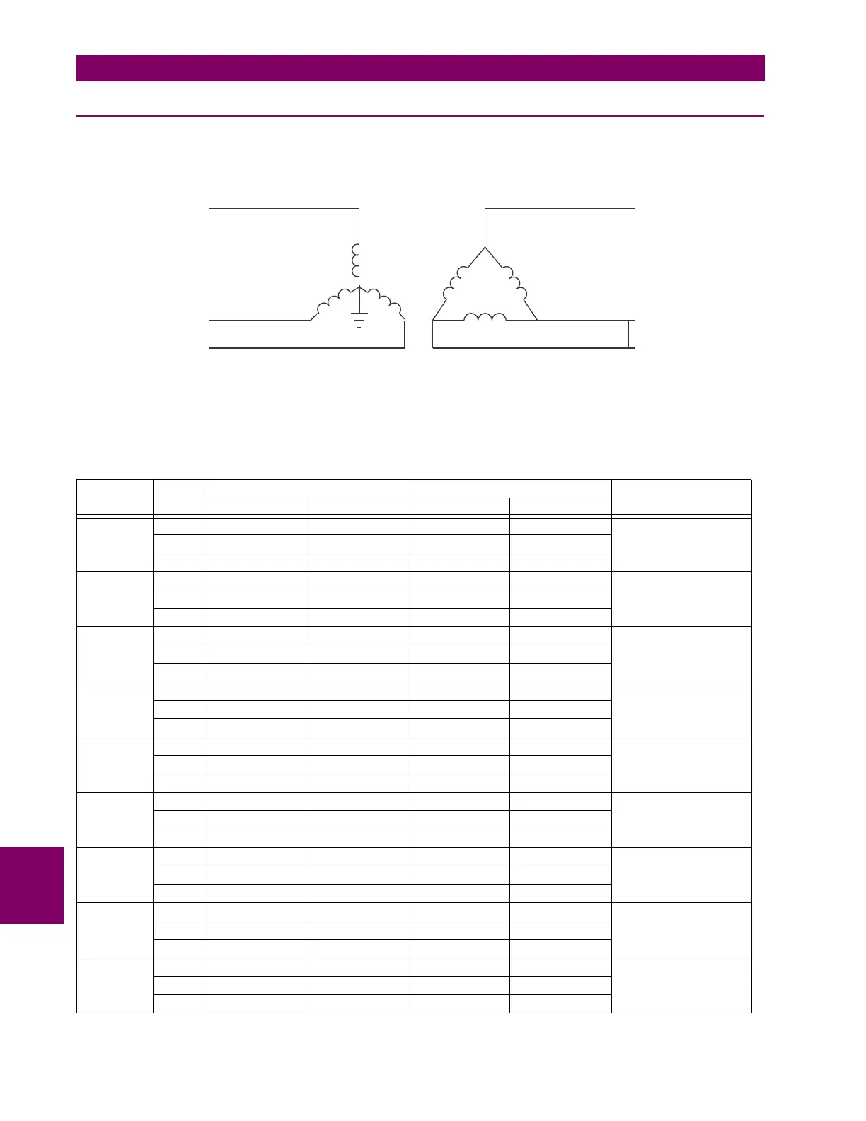
Transformer: Y/D30°, 20 MVA, 115/12.47 kv, CT1 (200:1), CT2 (1000:1)
Figure 9–4: CURRENT DISTRIBUTION ON A YG/D30° TRANSFORMER WITH AN a TO b FAULT ON THE LV SIDE
Three adjustable currents are required in this case. The Phase A and C Wye-side line currents, identical in magnitude but
displaced by 180°, can be simulated with one current source passed through these relay terminals in series. The second
current source simulates the Phase B primary current. The third source simulates the delta “b” and “c” phase currents, also
equal in magnitude but displaced by 180°.
TEST PHASE INJECTED CURRENT DISPLAYED CURRENT STATUS
W1 CURRENT W2 CURRENT DIFFERENTIAL RESTRAINT
Balanced
Condition
A 0.25 ∠0° 0 ∠0° 0 ∠0° 0 ∠0° Not Applicable
B0.5 ∠–180° 0.8 ∠0° 0 ∠0° 0.8 ∠0°
C 0.25 ∠0° 0.8 ∠–180° 0 ∠0° 0.8 ∠–180°
Min Pickup
change the
Min PKP to
0.2 pu
A 0.25 ∠0° 0 ∠0° 0 ∠0° 0 ∠0° Block
I
d
= 0.051 < Min PKP
B0.5 ∠–180° 0.95 ∠0° 0.154 ∠0° 0.948 ∠0°
C 0.25 ∠0° 0.95 ∠–180° 0.155 ∠0° 0.950 ∠–180°
Minimum
Pickup
A 0.25 ∠0° 0 ∠0° 0 ∠0° 0 ∠0° Operate
I
d
= 0.102 > Min PKP
B0.5 ∠–180° 1.05 ∠0° 0.253 ∠0° 1.049 ∠0°
C 0.25 ∠0° 1.05 ∠–180° 0.255 ∠0° 1.050 ∠–180°
Slope 1
return the
Min PKP to
0.1 pu
A 0.25 ∠0° 0 ∠0° 0 ∠0° 0 ∠0° Block
I
d
/I
r
= 13.2%
B0.5 ∠–180° 0.92 ∠0° 0.123 ∠0° 0.919 ∠0°
C 0.25 ∠0° 0.92 ∠–180° 0.123 ∠0° 0.919 ∠–180°
Slope 1 A 0.25 ∠0° 0 ∠0° 0 ∠0° 0 ∠0° Operate
I
d
/I
r
= 15.9%
B0.5 ∠–180° 0.95 ∠0° 0.153 ∠0° 0.948 ∠0°
C 0.25 ∠0° 0.95 ∠–180° 0.153 ∠0° 0.948 ∠–180°
Intermediate
Slope 1 & 2
A2 ∠0° 0 ∠0° 0 ∠0° 0 ∠0° Block
I
d
/I
r
= 84.3%
< 86.6%
computed
B4 ∠–180° 1 ∠0° 5.37 ∠–180° 6.37 ∠0°
C2 ∠0° 1 ∠–180° 5.37 ∠0° 6.37 ∠–180°
Intermediate
Slope 1 & 2
A2 ∠0° 0 ∠0° 0 ∠0° 0 ∠0° Operate
I
d
/I
r
= 87.5%
> 86.6%
computed
B4 ∠–180° 0.8 ∠0° 5.57 ∠–180° 6.37 ∠0°
C2 ∠0° 0.8 ∠–180° 5.57 ∠0° 6.37 ∠–180°
Slope 2 A 4 ∠0° 0 ∠0° 0 ∠0° 0 ∠0° Block
I
d
/I
r
= 93.7%
< Slope 2 = 95%
B8 ∠–180° 0.8 ∠0° 11.93 ∠–180° 12.73 ∠0°
C4 ∠0° 0.8 ∠–180° 11.93 ∠0° 12.73 ∠–180°
Slope 2 A 4 ∠0° 0 ∠0° 0 ∠0° 0 ∠0° Operate
I
d
/I
r
= 95.7%
> Slope 2 = 95%
B8 ∠–180° 0.6 ∠0° 12.13 ∠–180° 12.73 ∠0°
C4 ∠0° 0.6 ∠–180° 12.13 ∠0° 12.73 ∠–180°
828738A1.CDR
Y/d30° Transformer
F
I (f) = 0.5 pu –270°
A
∠
I (f) = 0.866 pu –90°
b
∠
I(f)=0
a
I (f) = 0.866 pu –270°
c
∠
I (f) = 1 pu –90°
B
∠
I (f) = 0.5 pu –270°
C
∠
A
B
C
A
B
C

 Loading...


