GE Multilin T35 Transformer Protection System 9-9
9 COMMISSIONING 9.2 DIFFERENTIAL CHARACTERISTIC TEST EXAMPLES
9
9.2.3 TEST EXAMPLE 2
D/YG30° TRANSFORMER WITH PHASE A TO GROUND FAULT ON THE GROUNDED WYE.
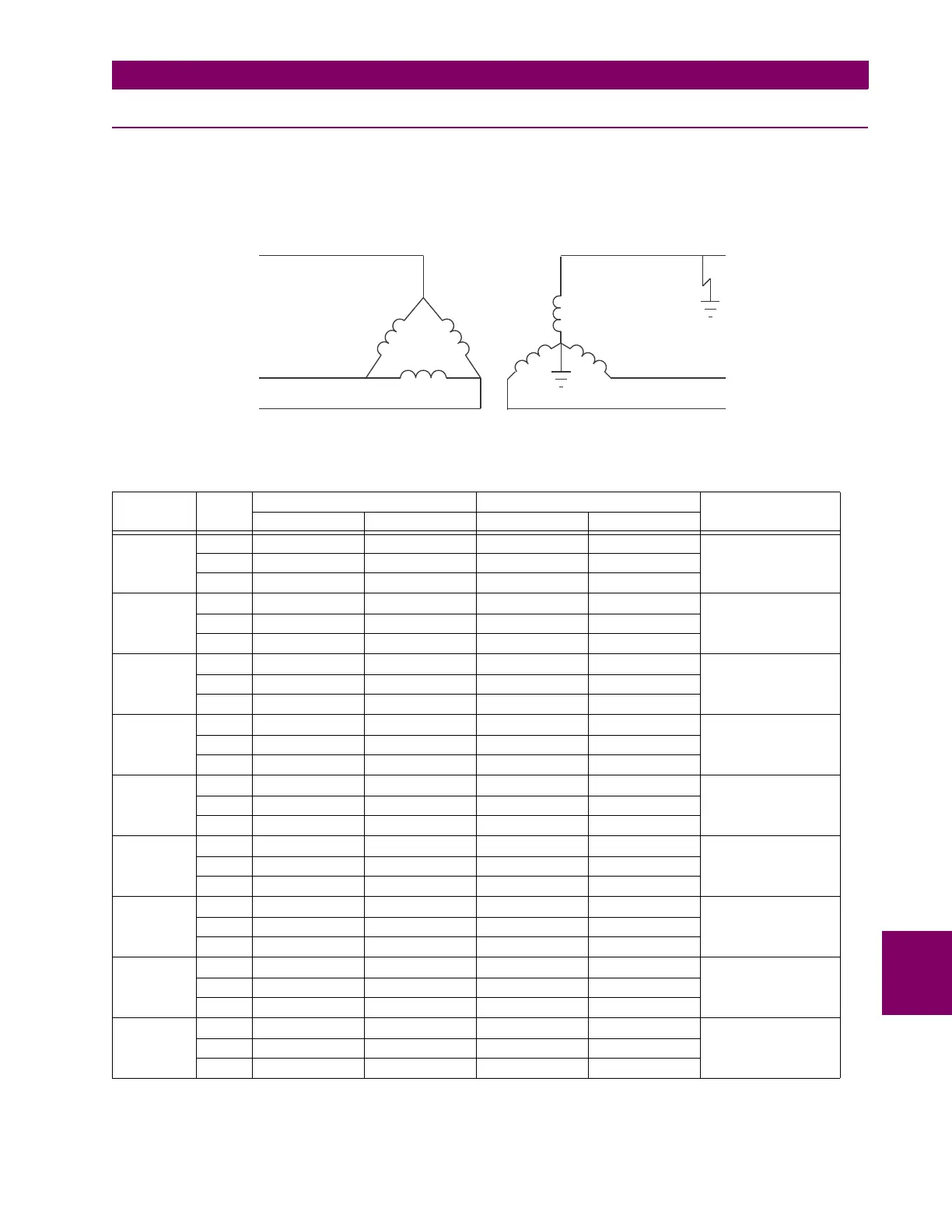
Transformer: D/y30°, 20 MVA, 115/12.47 kv, CT1 (200:1), CT2 (1000:1)
Figure 9–3: CURRENT DISTRIBUTION ON A D/YG30° TRANSFORMER WITH A LV-SIDE GROUND FAULT
TEST PHASE INJECTED CURRENT DISPLAYED CURRENT STATUS
W1 CURRENT W2 CURRENT DIFFERENTIAL RESTRAINT
Balanced
Condition
A 0.29 ∠0° 0.926 ∠–180° 0 ∠0° 0.5349 ∠–180° Not Applicable
B0 ∠0° 0 ∠0° 0 ∠0° 0 ∠0°
C 0.29 ∠–180° 0 ∠0° 0 ∠0° 0.5349 ∠0°
Minimum
Pickup
A 0.137 ∠0° 0.521 ∠–180° 0.048 ∠0° 0.3 ∠–180° Block
I
d
= 0.048 < Min PKP
B0 ∠0° 0 ∠0° 0 ∠0° 0 ∠0°
C 0.137 ∠–180° 0 ∠0° 0.048 ∠0° 0.3 ∠0°
Minimum
Pickup
A 0.108 ∠0° 0.521 ∠–180° 0.102 ∠0° 0.3 ∠–180° Operate
I
d
= 0.102 > Min PKP
B0 ∠0° 0 ∠0° 0 ∠0° 0 ∠0°
C 0.108 ∠–180° 0 ∠0° 0.102 ∠0° 0.3 ∠0°
Slope 1 A 0.4435 ∠0° 1.6 ∠–180° 0.110 ∠0° 0.9026 ∠–180° Block
I
d
/I
r
= 11.9%
B0 ∠0° 0 ∠0° 0 ∠0° 0 ∠0°
C 0.4435 ∠–180° 0 ∠0° 0 ∠0° 0 ∠0°
Slope 1 A 0.4425 ∠0° 1.7 ∠–180° 0.165 ∠0° 0.979 ∠–180° Operate
I
d
/I
r
= 16.8%
B0 ∠0° 0 ∠0° 0 ∠0° 0 ∠0°
C 0.4425 ∠–180° 0 ∠0° 0.165 ∠0° 0.979 ∠0°
Intermediate
Slope 1 & 2
A1.2 ∠0° 5 ∠–180° 0.675 ∠–180° 2.882 ∠–180° Block
I
d
/I
r
= 23.4%
B0 ∠0° 0 ∠0° 0 ∠0° 0 ∠0°
C1.2 ∠–180° 0 ∠0° 0.675 ∠0° 2.882 ∠0°
Intermediate
Slope 1 & 2
A1.1 ∠0° 5 ∠–180° 0.860 ∠–180° 2.882 ∠–180° Operate
I
d
/I
r
= 29.8%
B0 ∠0° 0 ∠0° 0 ∠0° 0 ∠0°
C1.1 ∠–180° 0 ∠0° 0.860 ∠0° 2.882 ∠0°
Slope 2 A 0.4 ∠0° 15 ∠–180° 7.915 ∠–180° 8.646 ∠–180° Block
I
d
/I
r
= 91.5%
B0 ∠0° 0 ∠0° 0 ∠0° 0 ∠0°
C0.4 ∠–180° 0 ∠0° 7.915 ∠0° 8.646 ∠0°
Slope 2 A 0.2 ∠0° 15 ∠–180° 7.918 ∠–180° 8.650 ∠–180° Operate
I
d
/I
r
= 95.7%
B0 ∠0° 0 ∠0° 0 ∠0° 0 ∠0°
C0.2 ∠–180° 0 ∠0° 7.916 ∠0° 8.650 ∠0°
828737A1.CDR
D/y30° Transformer
Fault
I (f) = 0.577 pu 0°
A
∠
I(f)=0
b
I(f)=1pu 0°
a
∠
I(f)=0
c
I(f)=0pu
B
I (f) = 0.577 pu –180°
C
∠
A
B
C
A
B
C

 Loading...


