5-246 T35 TRANSFORMER PROTECTION SYSTEM – INSTRUCTION MANUAL
CONTROL ELEMENTS CHAPTER 5: SETTINGS
5
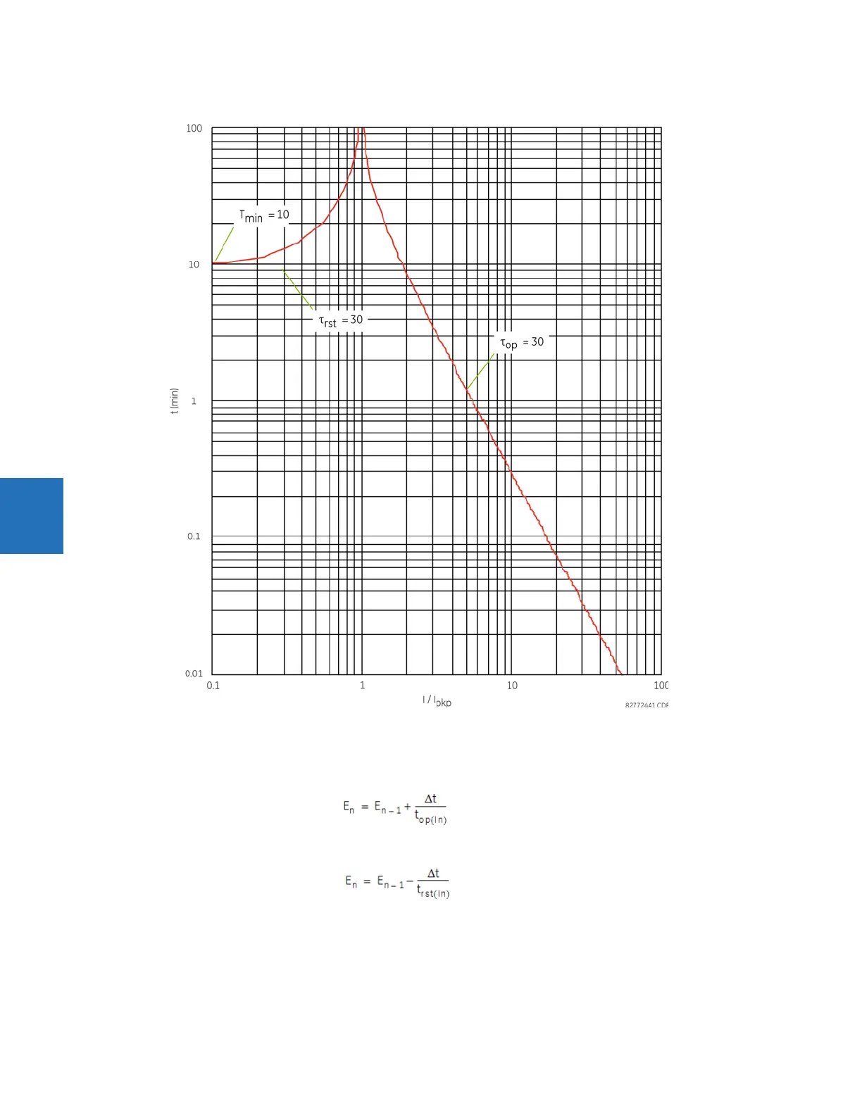
Figure 5-130: IEC 255-8 sample operate and reset curves
The thermal overload protection element estimates accumulated thermal energy E using the following equations
calculated each power cycle. When current is greater than the pickup level, I
n
> k × I
B
, element starts increasing the
thermal energy:
Eq. 5-48
When current is less than the dropout level, I
n
> 0.97 × k × I
B
, the element starts decreasing the thermal energy:
Eq. 5-49
where
∆t is the power cycle duration
n is the power cycle index
t
op(In)
is the trip time calculated at index n as per the IEC255-8 cold curve or hot curve equations
t
rst(In)
is the reset time calculated at index n as per the reset time equation