CHAPTER 5: SETTINGS INPUTS/OUTPUTS
T35 TRANSFORMER PROTECTION SYSTEM – INSTRUCTION MANUAL 5-247
5
I
n
is the measured overload RMS current at index n
E
n
is the accumulated energy at index n
E
n–1
is the accumulated energy at index n – 1
The thermal overload protection element removes the THERMAL PROT 1 OP output operand when E < 0.05. In case of
emergency, the thermal memory and THERMAL PROT 1 OP output operand can be reset using THERM PROT 1 RESET setting.
All calculations are performed per phase. If the accumulated energy reaches value 1 in any phase, the thermal overload
protection element operates and only resets when energy is less than 0.05 in all three phases.
Table 5-34: Typical time constants
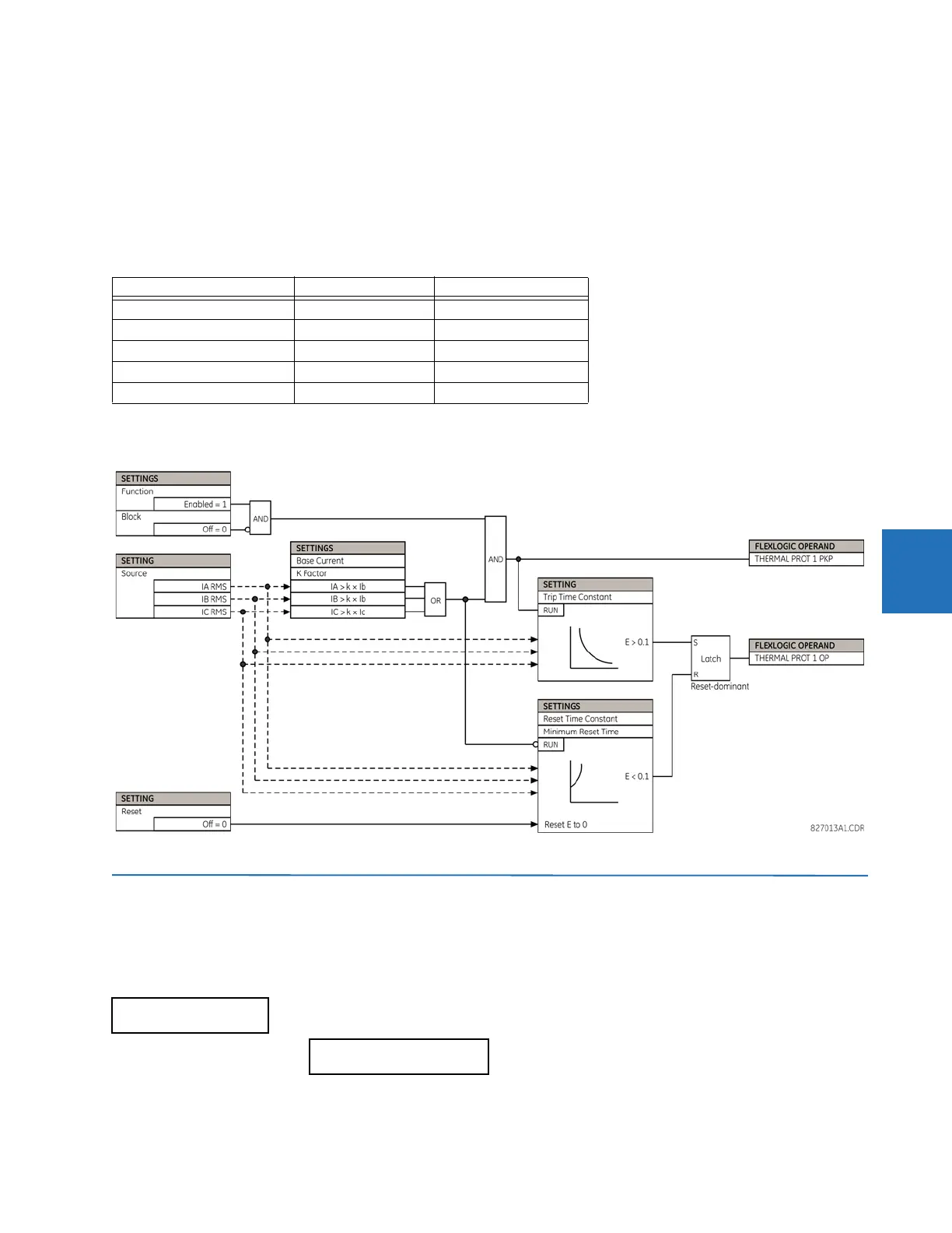
The figure shows the logic for the thermal overload protection element.
Figure 5-131: Thermal overload protection logic
5.9 Inputs/outputs
5.9.1 Contact inputs
SETTINGS INPUTS/OUTPUTS CONTACT INPUTS
Protected equipment Time constant Minimum reset time
Capacitor bank 10 minutes 30 minutes
Overhead line 10 minutes 20 minutes
Air-core reactor 40 minutes 30 minutes
Busbar 60 minutes 20 minutes
Underground cable 20 to 60 minutes 60 minutes
CONTACT INPUTS
CONTACT INPUT H5a