8-10 T35 TRANSFORMER PROTECTION SYSTEM – INSTRUCTION MANUAL
DIFFERENTIAL CHARACTERISTIC TEST EXAMPLES CHAPTER 8: COMMISSIONING
8
8.2.4 Test example 3
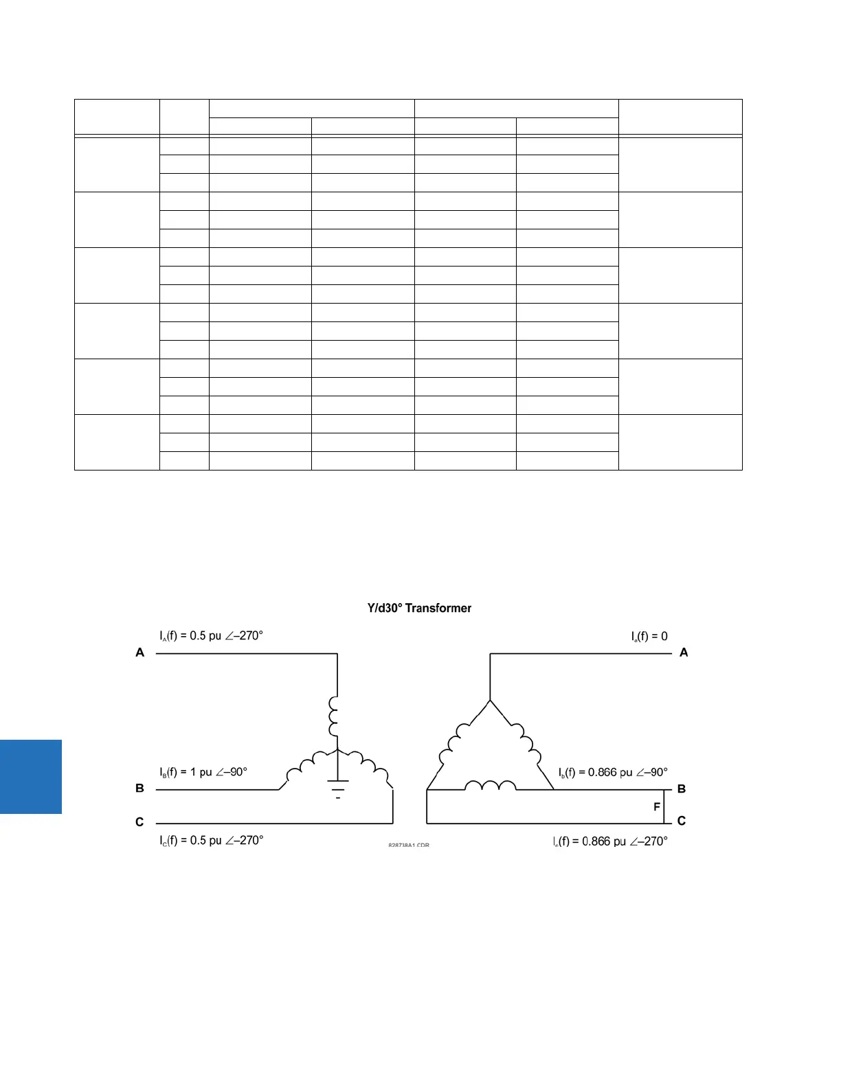
8.2.4.1 Yg/D30° transformer with phase B to C fault on the Delta side
Transformer data — Y/D30°, 20 MVA, 115/12.47 kv, CT1 (200:1), CT2 (1000:1)
Figure 8-4: Current Distribution on a Yg/D30° transformer with an a to b fault on the LV side
Three adjustable currents are required in this case. The Phase A and C Wye-side line currents, identical in magnitude but
displaced by 180°, can be simulated with one current source passed through these relay terminals in series. The second
current source simulates the Phase B primary current. The third source simulates the delta “b” and “c” phase currents, also
equal in magnitude but displaced by 180°.
Slope 1 A 0.4435 ∠0° 1.6 ∠–180° 0.110 ∠0° 0.9026 ∠–180° Block
I
d
/I
r
= 11.9%
B0 ∠0° 0 ∠0° 0 ∠0° 0 ∠0°
C 0.4435 ∠–180° 0 ∠0° 0 ∠0° 0 ∠0°
Slope 1 A 0.4425 ∠0° 1.7 ∠–180° 0.165 ∠0° 0.979 ∠–180° Operate
I
d
/I
r
= 16.8%
B0 ∠0° 0 ∠0° 0 ∠0° 0 ∠0°
C 0.4425 ∠–180° 0 ∠0° 0.165 ∠0° 0.979 ∠0°
Intermediate
Slope 1 & 2
A1.2 ∠0° 5 ∠–180° 0.675 ∠–180° 2.882 ∠–180° Block
I
d
/I
r
= 23.4%
B0 ∠0° 0 ∠0° 0 ∠0° 0 ∠0°
C1.2 ∠–180° 0 ∠0° 0.675 ∠0° 2.882 ∠0°
Intermediate
Slope 1 & 2
A1.1 ∠0° 5 ∠–180° 0.860 ∠–180° 2.882 ∠–180° Operate
I
d
/I
r
= 29.8%
B0 ∠0° 0 ∠0° 0 ∠0° 0 ∠0°
C1.1 ∠–180° 0 ∠0° 0.860 ∠0° 2.882 ∠0°
Slope 2 A 0.4 ∠0° 15 ∠–180° 7.915 ∠–180° 8.646 ∠–180° Block
I
d
/I
r
= 91.5%
B0 ∠0° 0 ∠0° 0 ∠0° 0 ∠0°
C0.4 ∠–180° 0 ∠0° 7.915 ∠0° 8.646 ∠0°
Slope 2 A 0.2 ∠0° 15 ∠–180° 7.918 ∠–180° 8.650 ∠–180° Operate
I
d
/I
r
= 95.7%
B0 ∠0° 0 ∠0° 0 ∠0° 0 ∠0°
C0.2 ∠–180° 0 ∠0° 7.916 ∠0° 8.650 ∠0°
Test Phase Injected current Displayed current Status
W1 current W2 current Differential Restraint