8-12 T35 TRANSFORMER PROTECTION SYSTEM – INSTRUCTION MANUAL
DIFFERENTIAL CHARACTERISTIC TEST EXAMPLES CHAPTER 8: COMMISSIONING
8
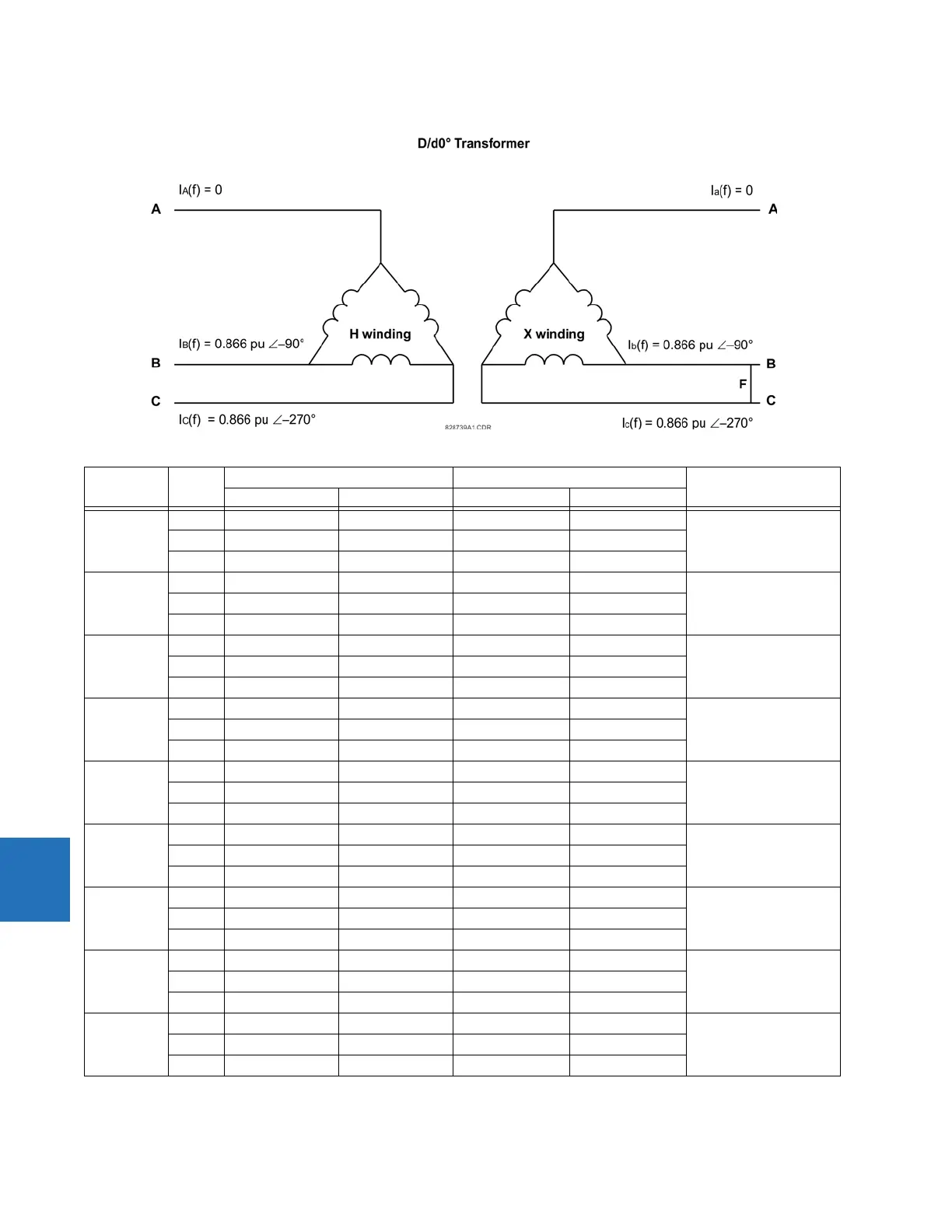
Figure 8-5: Current distribution of D/D transformer with an a to b fault on the LV side
Test Phase Injected current Displayed current Status
W1 current W2 current Differential Restraint
Balanced
Condition
A0 ∠0° 0 ∠0° 0 ∠0° 0 ∠0° Not Applicable
B 0.435 ∠–90° 0.8 ∠–270° 0 ∠0° 0.8 ∠–270°
C 0.435 ∠–270° 0.8 ∠–90° 0 ∠0° 0.8 ∠–90°
Min Pickup A 0 ∠0° 0 ∠0° 0 ∠0° 0 ∠0° Block
I
d
= 0.065 < Min PKP
B 0.09 ∠–90° 0.23 ∠–270° 0.065 ∠0° 0.230 ∠–270°
C 0.09 ∠–270° 0.23 ∠–90° 0.065 ∠0° 0.230 ∠–90°
Min Pickup A 0 ∠0° 0 ∠0° 0 ∠0° 0 ∠0° Operate
I
d
= 0.101 > Min PKP
B 0.21 ∠–90° 0.486 ∠–270° 0.102 ∠0° 0.486 ∠–270°
C 0.21 ∠–270° 0.486 ∠–90° 0.101 ∠0° 0.486 ∠–90°
Slope 1 A 0 ∠0° 0 ∠0° 0 ∠0° 0 ∠0° Block
I
d
/I
r
= 14% < 15%
B 0.651 ∠–90° 1.39 ∠–270° 0.195 ∠0° 1.39 ∠–270°
C 0.651 ∠–270° 1.39 ∠–90° 0.195 ∠0° 1.39 ∠–90°
Slope 1 A 0 ∠0° 0 ∠0° 0 ∠0° 0 ∠0° Operate
I
d
/I
r
= 16.8% > 15%
B 0.63 ∠–90° 1.39 ∠–270° 0.233 ∠0° 1.39 ∠–270°
C 0.63 ∠–270° 1.39 ∠–90° 0.233 ∠0° 1.39 ∠–90°
Intermediate
Slope 1 & 2
A0 ∠0° 0 ∠0° 0 ∠0° 0 ∠0° Block
I
d
/I
r
= 52.6%
< 60%
computed
B1.2 ∠–90° 4.63 ∠–270° 2.44 ∠–270° 4.63 ∠–270°
C1.2 ∠–270° 4.63 ∠–90° 2.44 ∠–90° 4.63 ∠–90°
Intermediate
Slope 1 & 2
A0 ∠0° 0 ∠0° 0 ∠0° 0 ∠0° Operate
I
d
/I
r
= 68.8%
> 60%
computed
B0.8 ∠–90° 4.63 ∠–270° 3.18 ∠–270° 4.63 ∠–270°
C0.8 ∠–270° 4.63 ∠–90° 3.18 ∠–90° 4.63 ∠–90°
Slope 2 A 0 ∠0° 0 ∠0° 0 ∠0° 0 ∠0° Block
I
d
/I
r
= 93.2%
< Slope 2 = 95%
B 0.315 ∠–90° 8.33 ∠–270° 7.77 ∠–270° 8.33 ∠–270°
C 0.315 ∠–270° 8.33 ∠–90° 7.77 ∠–90° 8.33 ∠–90°
Slope 2 A 0 ∠0° 0 ∠0° 0 ∠0° 0 ∠0° Operate
I
d
/I
r
= 96%
> Slope 2 = 95%
B 0.18 ∠–90° 8.33 ∠–270° 8 ∠–270° 8.33 ∠–270°
C 0.18 ∠–270° 8.33 ∠–90° 8 ∠–90° 8.33 ∠–90°