CHAPTER 10: MAINTENANCE REPLACE FRONT PANEL
T35 TRANSFORMER PROTECTION SYSTEM – INSTRUCTION MANUAL 10-19
10
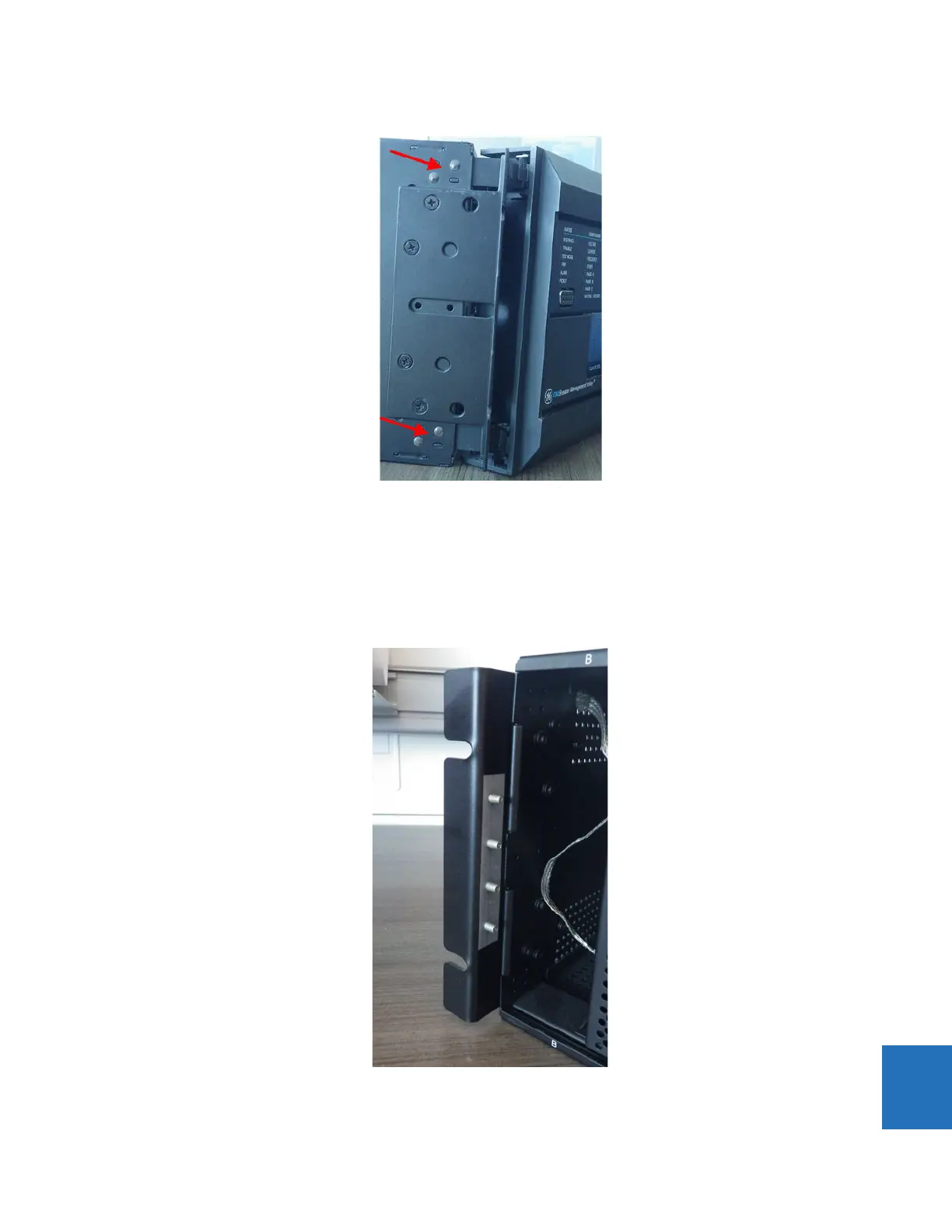
(note riveted hinges with red arrows - cannot replace this front panel)
The front panel has been removed.
To install the graphical front panel:
1. With power to the unit off, screw the left mounting bracket to the outside of the relay. The power supply module can
remain in the first slot.
Figure 10-19: Attach mounting bracket to relay on left side (no power supply module in first slot)
2. Screw the right mounting bracket to the right side of the relay.