Appendix Table
- 9 -
Appendix Table 1 CN1 pin layout
Terminal No.
Symbol
Function
CN1 - 1 D0
- 2 D1
- 3 D2
- 4 D3
- 5 D4
- 6 D5
- 7 D6
- 8 D7
- 9 D8
- 10 D9
CN1 - 11 D10
- 12 D11
- 13 D12
- 14 D13
- 15 D14
- 16 D15
< Low significant bit >
Parallel data
< Most significant bit >
- 17 LSB
Indicates low-order 8-bit when ON. (Use for 8-bit time
multiplexed mode)
- 18 STB
Loaded at the strobe ON to OFF edge. (Use for strobe
mode)
- 19 EX24
External 24V power supply input for the parallel data
input
- 20 EX0
External 24V power supply input common for the
parallel data input
CN1 - 21 PSO4 PSO4 output terminal (open collector)
- 22 COM1
- 23 COM1
PSO output terminal common
- 24 PSO5 PSO5 output terminal (open collector)
- 25 COM1
- 26 COM1
PSO output terminal common
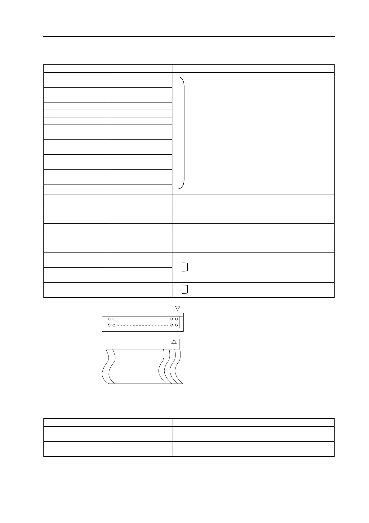
CN1
25
1
26 2
View from connector insertion side
1
Appendix Table 2 TB1 terminal functions
Terminal No.
Symbol
Function
TB1 - 1 EX24
External 24V power supply input for the parallel data
input
- 2 EX0
External 24V power supply input common for the
parallel data input
 Loading...


