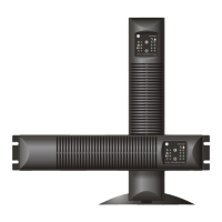
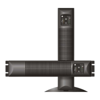
3.3.3 Rear panel
The figures on this page show a VH Series 3000 VA. The
differences with the rear panel - configuration of other
models is clearly indicated in the text below.
1 Input socket
AC mains supply to the UPS
700-2000 VA: smaller socket than shown here
2 Input breaker
Protects the UPS from damage caused by high
input currents
5
700-2000 VA: breaker has lower rating than
shown here
3 Appliance outlets - max. rating 10A
To connect the loads to the UPS.
700 VA: 2 outlets
1000-1500 VA: 4 outlets
2000-3000 VA: 6 outlets
3a Appliance outlet - max. rating 16A
4
(VH Series 3000 VA only)
To connect a heavy load to the UPS. An output
cord to connect a load to this outlet is not shipped
with the unit.
1
2
4 DC connector (not on VH Series 700 VA)
To connect a battery extension pack for extended
battery runtime
3a
5 Fan(s)
6
Electronically controlled cooling fan(s). Make sure
ventilation air can move freely around and
through the UPS.
3
7
6 USB port
See 5.1 for more information
7 RJ 11 port
See 5.2 for more information
fig. 3.3.3.a: rear panel - tower (3000 VA model)
5 4 1 3a 3
6 7 2
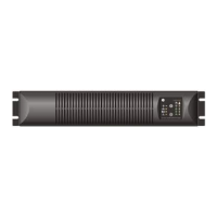
fig. 3.3.3.b: rear panel - rackmount (3000 VA model)
modifications reserved
OPM_VHE_XXX_0K7_3K0_XGB_V010
8 User manual VH Series 700-3000 UPS 1.0 (GB)
 Loading...