– 39 –
Inverter
The inverter receives commands from the control
board and controls motor operation. The inverter is
enclosed in a protective housing and is located on
the chassis, under the left side of the outer tub. It is
inserted in 2 guides at the rear and held in place by
a single Phillips-head screw at the front.
For the inverter to operate the motor correctly
requires a supply voltage of 120 VAC, DC input from
the control board, and the three motor windings
intact.
Specifi c failures associated with the inverter can
initiate error codes E43, E4A, E4B, E4C, E4E, E4F, and
E53. (See Service Test Mode.)
To check the inverter:
Remove the service panel. (See Service Panel.)
Press the 4 tabs inward and remove the junction
box cover.
Enter test mode t10, t11, or t14.
Check for 120 VAC between the blue and red
wires at the AC input harness.
Note: The 120 VAC inverter supply voltage is present
only when the motor is supposed to be operating.
Unplug washer, then check motor resistance.
(See Motor Assembly.)
If 120 VAC is present at the AC input harness and
motor resistance is correct, replace the inverter.
Note: If the inverter overheats, the washer will stop
for 5 minutes.
1.
2.
3.
4.
5.
6.
(Continued Next Page)
Disconnect the motor wire harness.
Note: The motor wire harness is soldered to the
inverter. Any fault in the inverter or motor wire
harness requires inverter replacement.
4.
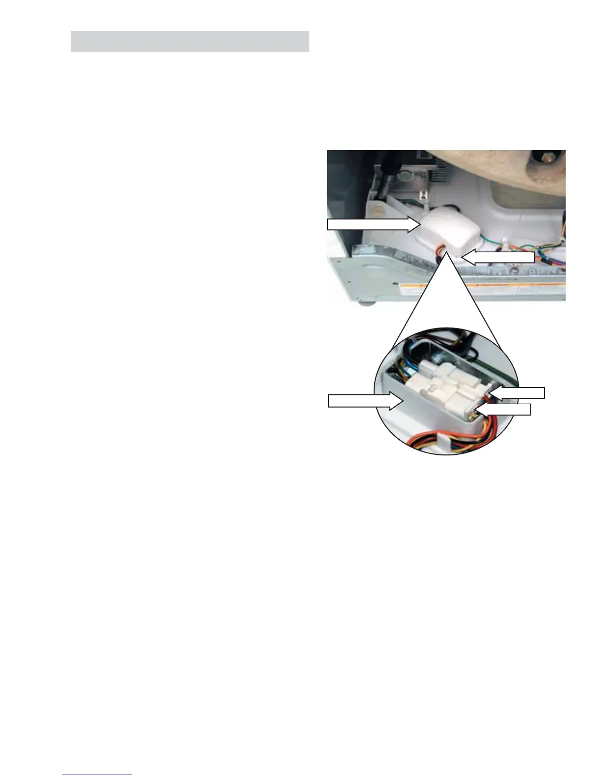
To remove the inverter:
Remove the service panel. (See
Service Panel.)
Press the 4 tabs inward and remove the junction
box cover.
Disconnect the AC and DC input wire harnesses
contained in the junction box.
1.
2.
3.
Junction Box Cover
Tab (1 of 4)
AC Input
DC Input
Junction Box
 Loading...