– 41 –
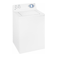
Note: The sensor and sensor wiring can be checked
at the control board. Check for a resistance value
of approximately 118 Ω resistance between the 2
yellow wires located on the wire harness located at
P9.
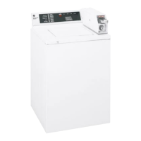
On the inverter board, check for an approximate
resistance value of 6 ohms between any two of
the three terminals:
A to B (Blue to white) - 6 Ω
A to C (Blue to red) - 6 Ω
B to C (White to red) - 6 Ω
5.
•
•
•
B
C
A
P9
To remove the motor:
Remove the 4 Phillips-head screws from the
cabinet rear cover.
Pull the cover outward from the middle.
1.
2.
(Continued Next Page)
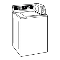
Note: The belt is elastic and is designed to be
removed and installed in this manner.
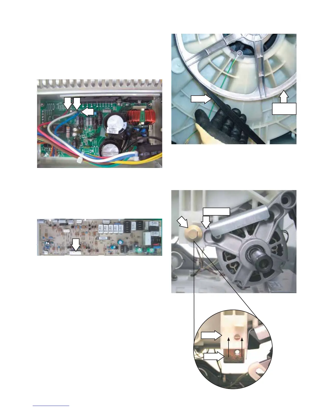
Remove the
1
/
2
-in. bolt from the threaded plate
that holds the motor arm to the outer tub.
4.
Remove the belt by turning the tub drive pulley
and rolling the belt off the pulley.
3.
Slot
Plate
Motor Arm
Belt
Tub Drive
Pulley
 Loading...