14
D
GB
F
E
09702-09.2013-DGbF
5| Compressor assembly
5.6 Operating the shut-off valves
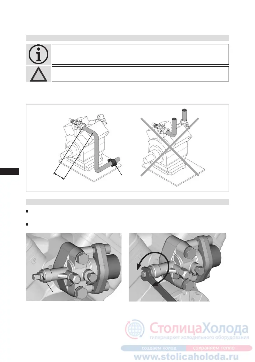
5.5 Laying suction and discharge lines
INFO! Proper layout of the suction and discharge lines directly after
the compressor is integral to the system’s smooth running and
vibration behaviour.
ATTENTION! Improperly installed pipes can cause cracks and tears, the result
being a loss of refrigerant.
A rule of thumb:
Always lay the rst pipe section starting from the shut-off valve downwards
and parallel to the drive shaft.
Fig. 18
Rigid
Fixed point
As short as
possible
Valve spindle seal
Before opening or closing the shut-off valve, release the valve spindle seal by approx. ¼ of a turn
counter-clockwise.
After activating the shut-off valve, re-tighten the adjustable valve spindle seal clockwise.
Fig. 19 Fig. 20
loosen
tighten
 Loading...