4
8164-9001-400 / 1198
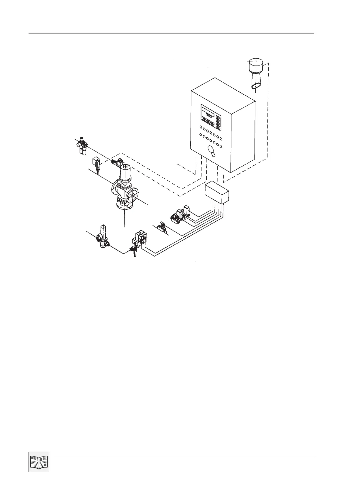
1.4 General layout plan
Fig. 3
9
1
8
14
11
13
10
12
7
3
2
A
C
6
5
4
B
D
A Water
B Compressed air
C Dirty oil feed
D Clean oil discharge
1 Control unit C7-623 and motor control for centrifuge
Motor control feed pump
Motor control sludge pump
2 Water pressure reducer
3 Feed assembly with solenoid valve for
filling, displacement and operating water
4 Compressed air control unit
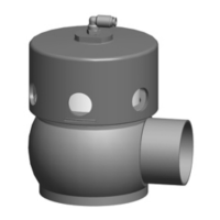
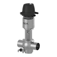
5 Pneumatic 3/2-way valve with
manual adjustment and solenoid valve for control air
(fitted in the dirty oil line of the separator)
6 PT 100 oil feed min./max. temperature monitoring
7 Pressure switch (for monitoring the clean oil discharge)
8 Connections for electrical power supply
9 Klaxon
10 Water discharge valve
11 Circuit valve
12 Pressure switch - sludge space monitoring
13 Water sensor
14 Terminal box (fitted to separator)
On special order only.