Do you have a question about the GEA VARIVENT D and is the answer not in the manual?
Defines the intended purpose of the valve and user responsibilities.
Specifies qualifications and training required for operating and maintenance personnel.
Outlines rules for modifications, approved spare parts, and accessories.
General obligations for valve operation and adherence to safety regulations.
Explains symbols used in the manual for process steps and information.
Guidelines for safe handling, storage, and inspection of the valve.
Procedures for inspecting the valve upon receipt for damage or missing parts.
Guidelines for safe handling and transportation of the valve to prevent damage.
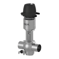
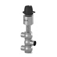
Description of the valve's physical components and layout.
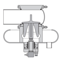
Explanation of the valve's operational principles and modes.
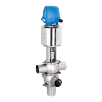
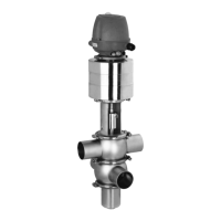
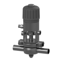
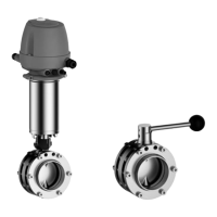
Overview of different VARIVENT valve configurations and their features.
Details on specific sterile lock configurations for the valve.
Explains the mixproof shut-off functionality of the valve.
Describes the spray cleaning process for the B_L valve type.
Method for cleaning valve seats and leakage chambers by lifting valve discs.
Information on adjusting the lower valve disk for optimal lift stroke.
Details on the actuator's spring-closing function and status indicators.
Guidelines for installing the valve in the correct upright position for proper drainage.
Instructions for connecting and handling the control module and associated safety precautions.
Information on installing valves with detachable housing connections.
Procedures and safety precautions for welding the valve into the pipe system.
Data on compressed air needed for different actuator types and strokes.
Guidance on correctly connecting pneumatic hoses according to diagrams.
Steps for initial setup, checking system integrity, and initial valve actuation.
Procedures for regular cleaning of product-contact parts and valve housings.
Provides typical cleaning parameters for dairy and brewery applications.
Describes methods for cleaning the leakage outlet system using spray nozzles.
Details on cleaning sensitive media or crystallizing substances using lift cleaning.
Explains lift cleaning with spray for critical media like sticky or viscous products.
Information on the passivation process typically used for pipes and tanks.
Schedule and procedure for checking valve seals and overall function.
Regular checks for sealing rings, O-rings, and V-rings in product contact areas.
Checks for operating pressure, filter, hose connections, and solenoid valve function.
Checks for cable gland tightness and connections at the terminal.
Steps to remove the control module from the valve.
Procedure for carefully removing the valve insert from the housing.
Detailed steps for removing the valve insert from the actuator assembly.
Instructions for disassembling the actuator, including specific components.
Instructions for cleaning valve components, emphasizing precision parts.
Guidelines for replacing defective seals and O-rings, recommending original spare parts.
Steps and tools required for replacing the V-ring seal.
Instructions for lubricating and installing the balancer component.
Procedure for measuring and setting the valve disk lift stroke.
Correct procedure for installing seat rings, noting orientation marks.
Steps to check the valve's total stroke and proximity switch function.
Table of valve dimensions for different types and sizes.
Specifies materials used for parts in contact with the product.
Requirement for upright installation to ensure proper isolation chamber drainage.
Specifies operating temperature limits and special handling for low temperatures.
Details on proximity switch operating temperature and limitations.
Defines temperature ranges for product and operation based on sealing material.
Maximum product pressure specifications.
Specifies control air pressure requirements and quality standards.
Air quality requirements regarding solid particle content.
Air quality requirements regarding water content (dew point).
Air quality requirements regarding oil content.
Specifications for air hose material and dimensions.
Specifies the required hose connections for CIP cleaning.
Recommended pressure range for effective CIP cleaning.
Table showing CIP hose material resistance to various media, pressures, and temperatures.
Identifies the machine as a Valve with actuator, VARIVENT®.
Lists the applicable EC directives, primarily the Machinery Directive 2006/42/EC.
Lists harmonized standards applied, such as DIN EN ISO 12100.
Identifies the authorized person responsible for technical documentation.
| Type | Control Unit |
|---|---|
| Material | Stainless steel |
| Hygiene Standards | EHEDG, 3-A |
| Housing material | Stainless steel |
| Sealing material | EPDM |
| Operating temperature | -10 °C to +120 °C |
| Model | GEA VARIVENT D |