Page 9
VII. CHARTS WHICH PRESENT OPERATION OF PARTICULAR
ELEMENTS OF THE UNIT
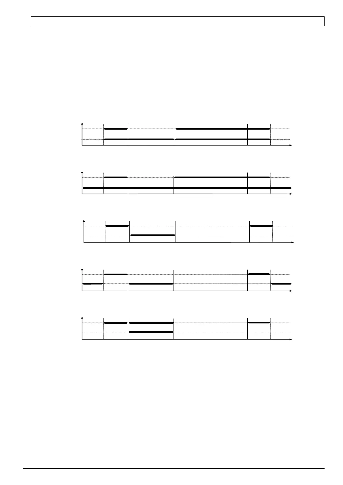
Thick line means that the unit is on and interrupted line means that the unit is off.
The square ‘stop’ means that the compressor is off and ‘operation’ that it is on because programmed
temperature has been exceeded, taking into account the value of programmed hysteresis parameter ‘d3’.
AN ERROR IN THE SETUP OF PARAMERS WILL CAUSE WRONG OPERATION OF THE UNIT!!!
1.
ventilator which operates together with compressor ‘r1’=01
t=0 (c3 of no im portance)
C O M PR ESSO R
VENTILATOR
stop operation D EFRO STIN G E N D O F D E FRO STIN G operation stop
2.
ventilator which operates all the time ‘r1’=02,
t=0 (c3 of no importance)
C O M P R E SSO R
V E N T ILA T O R
sto p operation D E FR O S T IN G EN D O F D E FR O S T IN G operation stop
3.
evaporator heater ‘r1’=03,
t=c3
C O M P R E SSO R
H E A T E R
sto p operation D E FR O S T IN G E N D O F D E F R O ST IN G o peration stop
4.
tray heater ‘r1’=04,
t=c3
C O M P R E SSO R
TRAY HEATER
sto p operation D E FR O S T IN G E N D O F D E FR O ST IN G operation stop
5.
valve ‘r1’=05,
t=c3
C O M P R E SSO R
V A L V E
sto p operation D E FR O S T IN G EN D O F D E FR O ST IN G operation stop
ª
 Loading...