SERVICE MANUAL FOR PRODUCERS SBR TYPE GC201 Page 11
PPUH „GECO” EDITION I PRINTOUT DATE 18-04-30
example 2.
Hysteresis of ‘d3’ is set as 4ºC
For the above setting of the hysteresis the
parameter ‘d0’ should be set as 4ºC and ‘d1’ as 8ºC
example 4.
Hysteresis of ‘d3’ is set as 5ºC
For the above setting of the hysteresis the parameter
‘d0’ should be set as 4ºC and ‘d1’ as 7ºC
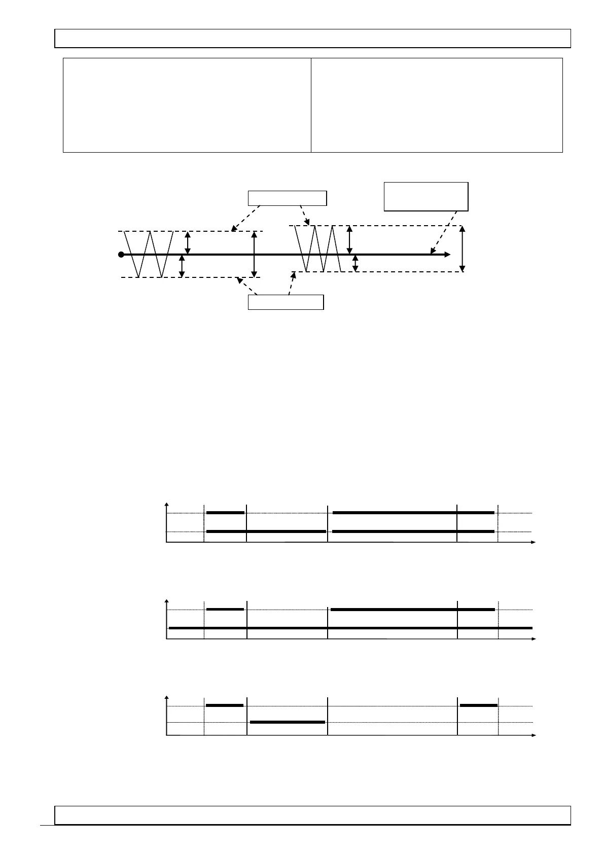
CHARTS WHICH PRESENT OPERATION OF PARTICULAR ELEMENTS OF THE UNIT
Thick line means that the unit is on and interrupted line means that the unit is off.
The square ‘stop’ means that the compressor is off and ‘operation’ that it is on because programmed
temperature has been exceeded, taking into account the value of programmed hysteresis parameter ‘d3’.
AN ERROR IN THE SETUP OF PARAMERS WILL CAUSE WRONG OPERATION OF THE UNIT!!!
1. ventilator which operates together with compressor ‘r1’=01
t=0 (c3 of no importance)
COMPRESSOR
VENTILATOR
stop operation DEFROSTING END OF DEFROSTING operation stop
2. ventilator which operates all the time ‘r1’=02,
t=0 (c3 of no importance)
COMPRESSOR
VENTILATOR
stop operation DEFROSTING END OF DEFROSTING operation stop
3. evaporator heater ‘r1’=03,
t=c3
COMPRESSOR
HEATER
stop operation DEFROSTING END OF DEFROSTING operation stop
4. tray heater ‘r1’=04,
Temperature set
by the user
 Loading...