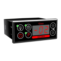
page 6 SERVICE MANUAL FOR PRODUCERS SBR TYPE GC201
PPUH „GECO” EDITION I PRINTOUT DATE 18-04-30
V. INSTALLATION OF SENSORS.
1. For every type of the cooling unit the place of fixing of chamber and evaporator sensor and setting of
system parameters GC201 should be chosen through experimentation. It is absolutely forbidden to change
the location or the method of fixing of sensors and settings of GC201 without doing new tests related to
temperature stabilisation and to the course of defrosting of the unit!!!
2. The chamber sensor must be fixed in such a way that it does not touch foods and is not exposed to damage
during cleaning of the unit. A special plastic handle can be used to fix this sensor. Such solution causes
quick (time delay on/off see VI, item 5) the reaction of the sensor and of the whole thermostat to a change
of air temperature in the unit. If it is recommended or necessary to slow down and ‘smooth out’ reaction
time of the sensor to temperature changes, it is advisable to screw it to a metal element of the unit.
3. Evaporator sensor should be fixed in the way which assures maximally good and sure contact with the
evaporator slat and in the place where ice keeps longest during defrosting. Its fixing should prevent its
pushing out by growing ice. If possible, sensors should be fixed vertically so that the cable goes out of a
sensor at its bottom.
4. Sensor cables can be shortened or lengthened in any way according to the following rules:
- Cable sensor should not be cut at a distance below 0.5 m from the shell
- It is not recommended to lengthen sensor cable above 20 m.
- SENSOR CABLES CAN BE CONNECTED TO SENSOR CLAMPS IN THE OPERATING UNIT IN ANY WAY!!!
(similarly to the method of plugging of the plug in the socket ~230V)
- cable OMY 2x0.5 mm is recommended for cable lengthening,
- if cables are lengthened their connection should be done very carefully, every pair of veins should be
soldered and heat-shrinking sheaths should be put on them. Then the place of connection should be
filled with water-resistant silicone and one more heat-shrinking sheath should be put on..
- endings of cable connected to the independent control unit should be tinned.
VI. OPERATION METHOD
A - General information
1. Start after connection to mains
When the unit is connected to mains a 3-second start procedure takes place during which two dots appear on
the display for a second, controller program version appears for another second and then two dots appear
again. At that time none of controlled units is switched on.