SERVICE MANUAL FOR PRODUCERS SBR TYPE GC201 Page 13
PPUH „GECO” EDITION I PRINTOUT DATE 18-04-30
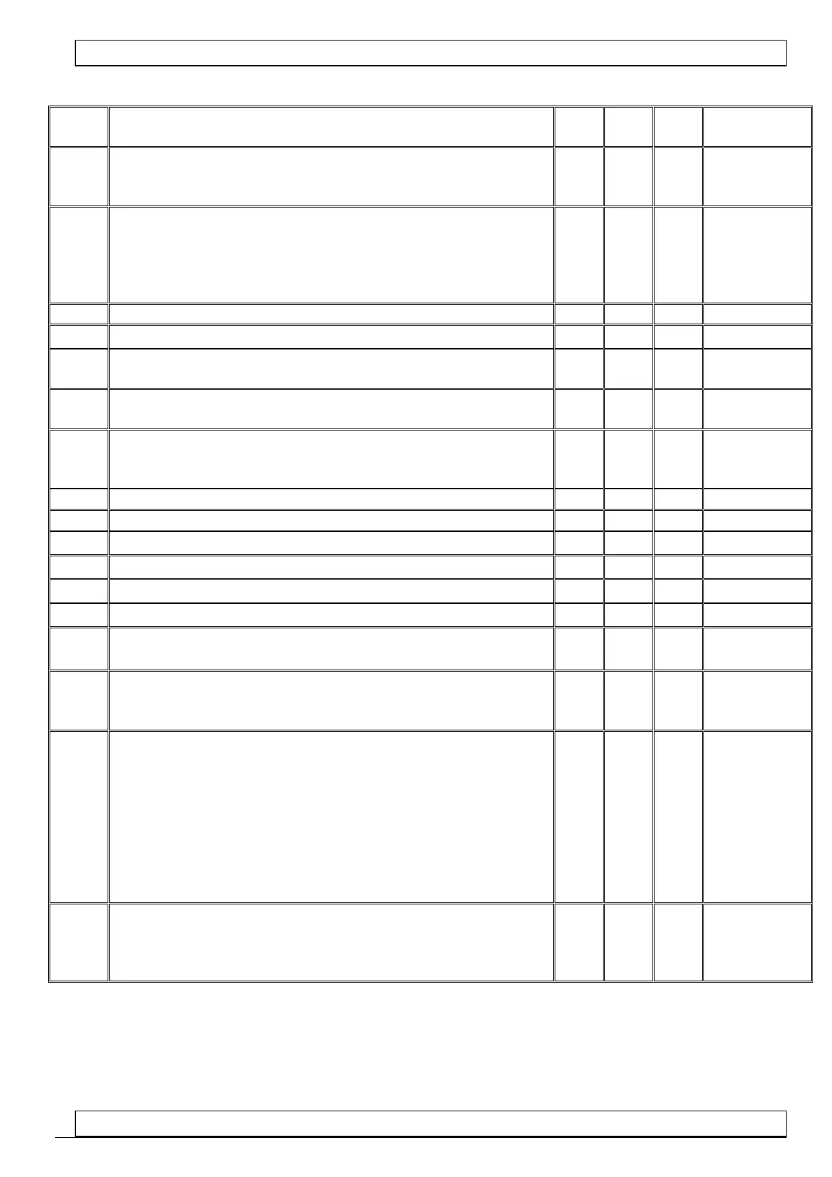
Table 2: Significance of parameters
How often defrosting will take place
00 – there will be no automatic defrosting, only manual defrosting!!!
-01 there will be no automatic or manual defrosting!!!
For r2 = 0 the maximum defrosting time, if the evaporator does not
reach the set temperature (parameter d2); for r2 = 1 defrosting time
not conditioned by parameter d2; Warning!!! If this parameter is set
to "-01" there will be no time limit
Minimal time of compressor stoppage
Time of evaporator dripping
Maximal time of operation of compressor
0 – no testing (this parameter is off)
Time of compressor stoppage after switching on of protection from
parameter ‘c5’
Time during which after the end of defrosting (parameter ‘c3’)
temperature measured just before the beginning of defrosting will
be displayed
Compressor operation time with damage of control sensor
Compressor stoppage time with damage of control sensor
Minimal temperature for a client to set
Maximal temperature for a client to set
Evaporator temperature at which defrosting will stop
Value of rescaling of chamber sensor in comparison with actually
measured temperature
Temperature in the chamber whose exceeding makes alarm A4
switch on.
Unit connected to other transformer:
00 – lighting
01 – ventilator operating with compressor
02 – ventilator operating all the time
03 – evaporator heater
04 – tray heater
05 – valve
06 – compressor transformer with more power - ! equipment
replacement required ! ref. to GC201.03
00
(for version
GC201.02
and GC201.04)
01
(for version
GC201.01)
06
(for version
GC201.03) )
Operation of the evaporator sensor:
0 - the sensor is supported
1 - the sensor is blocked