SCCB TYPE G-203-P00 Service Manual for Producers Page 13
PPUH „GECO” EDITION I PRINTOUT DATE 2014-04-15
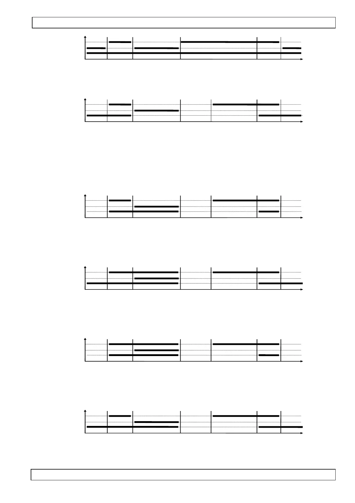
t=0 (c3 i c4 bez znaczenia)
COMPRESSOR
OUTFL. HEATER
FAN
Stop Operation DEFROSTING DEFROSTING EXITING Operation Stop
6. Defrosting through the heater, ‘r1’=02, fans operate permanently after turning on the unit ‘r2’=01
t=c3 t=c4
COMPRESSOR
HEATER
FAN
Stop Operation DEFROSTING DEFROSTING EXITING Operation Stop
The following charts apply to the ‘r0’=01 parameter.
7. Defrosting with heater ‘r1’=02, fans run only together with compensator ‘r2’=00, fan on during
defrosting ‘r0’=01
t=c3 t=c4
COMPRESSOR
HEATER
FAN
Stop Operation DEFROSTING DEFROSTING EXITING Operation Stop
8. Defrosting with warm steam ‘r1’=03, fans run all the time after equipment powers on ‘r2’=01, fan on
during defrosting ‘r0’=01
t=c3 t=c4
COMPRESSOR
VALVE
FAN
Stop Operation DEFROSTING DEFROSTING EXITING Operation Stop
9. Defrosting with warm steam ‘r1’=03, fans run only together with compensator ‘r2’=00, fan on during
defrosting ‘r0’=01
t=c3 t=c4
COMPRESSOR
VALVE
FAN
Stop Operation DEFROSTING DEFROSTING EXITING Operation Stop
10. Defrosting with heater ‘r1’=02, fans run all the time after equipment powers on ‘r2’=01, fan on
during defrosting ‘r0’=01
t=c3 t=c4
COMPRESSOR
HEATER
FAN
Stop Operation DEFROSTING DEFROSTING EXITING Operation Stop
 Loading...