Page 12 Service Manual for Producers SCCB TYPE GC203
PPUH „GECO” EDITION I PRINTOUT DATE 2018-07-26
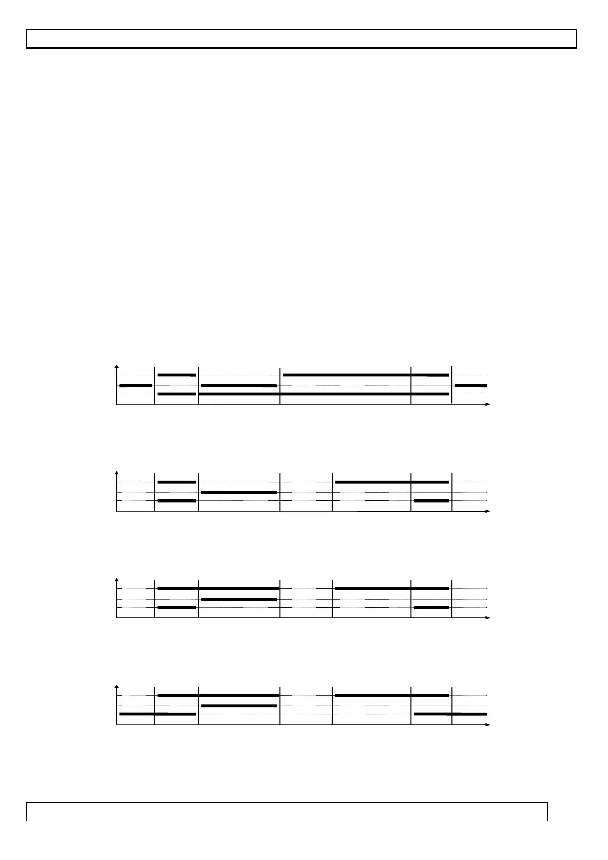
VII. UNIT PARTICULAR COMPONENTS ACTIVATION GRAPHS
A thick line denotes activation, while the dashed one means deactivation of the particular equipment. The
defrosting exiting mode comprises two Phases – see Chapter VI B-Defrosting.
The “Stop” field denotes deactivation, while the “Operation” field denotes the compressor’s activation due to
exceeding the preset temperature, taking account of the “d3’ preset hysteresis value. The heater on the figure
‘1’ is intended for heating the tray and/or the water discharge hose from the evaporator. The heater on figure
’5’ is intended only for heating the water discharge hose from the evaporator.
IF ERRONEOUS PARAMETERS ARE SET, THE UNIT WILL FAIL TO OPERATE PROPERLY !!!
The first 6 charts apply to the setting of ‘r0’ = 00 – the fan is on during defrosting, like in the 01
program version.
1. Defrosting through the compressor stop, ‘r1’=01, fans operate only together with the compressor,
‘r2’=00
t=0 (c3 and c4 immaterial)
COMPRESSOR
TRAY HEATER
FAN
Stop Operation DEFROSTING DEFROSTING EXITTING Operat. Stop
2. Defrosting through the heater, ‘r1’=02, fans operate only together with the compressor ‘r2’=00
t=c3 t=c4
COMPRESSOR
HEATER
FAN
Stop Operation DEFROSTING DEFROSTING EXITING Operation Stop
3. Warm vapour defrosting ‘r1’=03, fans operate only together with the compressor ‘r2’=00
t=c3 t=c4
COMPRESSOR
VALVE
FAN
Stop Operation DEFROSTING DEFROSTING EXITING Operation Stop
4. Warm vapour defrosting ‘r1’=03, fans operate permanently after turning on the unit, ‘r2’=01
t=c3 t=c4
COMPRESSOR
VALVE
FAN
Stop Operation DEFROSTING DEFROSTING EXITING Operation Stop
5. Defrosting through the compressor stop ‘r1’=01, fans operate permanently after turning on the unit
‘r2’=01
 Loading...