• Prot
72
(*) - Fixed scale limits
- Retransmission output not available with ON/OFF control action
-1999...9999
Prot
42
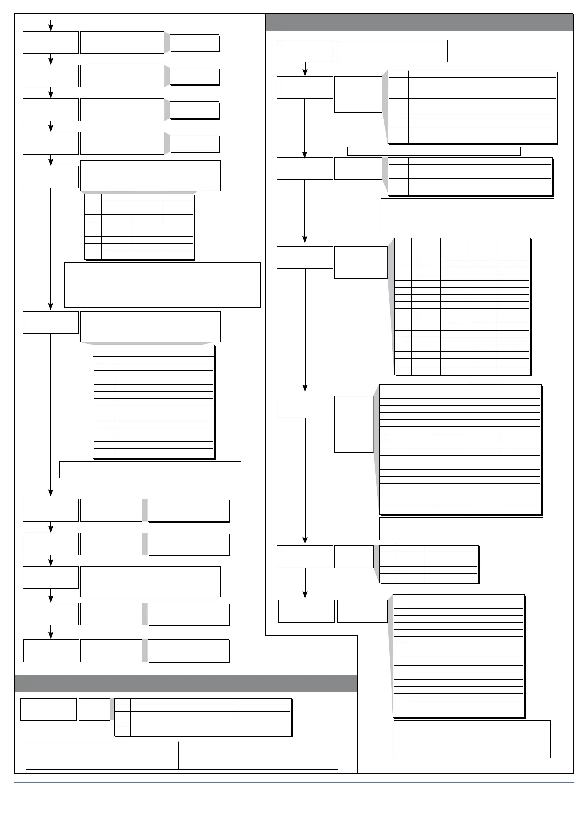
Protection
code
Prot Dispaly Modification
0 SP, InP2, alarms, OutP, INFO, DATA SP, alarms, DATA
1 SP, InP2, alarms, OutP, INFO, DATA SP, alarms
2 SP, InP2, alarms, OutP, INFO SP
3 SP
+4 to disable InP, Out +32 disable manual power latching
+8 to disable CFG, Ser +64 to disable manual power modification
+16 to disable SW “power-up - power down”
x.an.i
An.o.2
l.an.2
x.an.2
An.o.i
l.an.i
1. ... 200 sec
1. ... 200 sec
(0.1...20.0 sec)
1. ... 200 sec
1. ... 200 sec
Fault action (sets state in case of probe fault)
Alarm outputs AL1, AL2, AL3;
Select intrinsic safety
Minimum limit of
analogue repetition
signal output 1
Note:
1) In case of broken probe, logic state of individual alarm assumes
selected logic value without consideration of alarm type (direct or
inverse): ON=alarm active; OFF=alarm inactive
2) Assign alarms to available outputs by entering codes rLo1, rLo2, rLo3,
rLo4.
Maximum limit of
analogue repetition
signal output 1
An.o.x Reference value
0 PV - process variable
1 SSP - active setpoint
2 -
3 InP.2 - aux input
4 Deviation (SSP-PV)
5 HEAT (*)
6 COOL (*)
7 AL1 (alarm point)
8 AL2 (alarm point)
9 AL3 (alarm point)
10 AL.HB - (alarm point)
11 Value acquired from serial line
12 Setpoint slaved to programmer
Out W1
Assignment of signal or reference value: PV, SP,
SP-PROG, DEV+, DEV-, IN.AUX, HEAT, COOL,
AL1, AL2, AL3, serial line value
Cycle time for OUT4 relay or
logic output = HEAT or COOL
74
75
76
77
78
_rEL. Alarm 1 Alarm 2 Alarm 3
0 OFF OFF OFF
1 ON OFF OFF
2 OFF ON OFF
3 ON ON OFF
4 OFF OFF ON
5 ON OFF ON
6 OFF ON ON
7 ON ON ON
-1999...9999
An.o.1, An.o.2
+ 16 for inverted output with respect to reference value
+ 32 for output with 2...10V, 4...20mA signal
71
73
Cycle time for OUT1 relay or
logic output = HEAT or COOL
Cycle time for OUT2 relay or
logic output = HEAT or COOL
Cycle time for OUT3 relay or
logic output = HEAT or COOL
Minimum limit of
analogue repetition
signal output 2
Maximum limit of
analogue repetition
signal output 2
Out W2.
Assignment of signal or reference value: PV, SP,
SP-PROG, DEV+, DEV-, IN.AUX, HEAT, COOL,
AL1, AL2, AL3, serial line value
79
80
81
• Hrd
sp.pr
hrd.i
hrd.2
Hrd
Hardware configuration
Installation of aux
input, digital inputs,
serial interface
Installation
of relay,
logic outputs
MAIN, AL1,
AL2, AL3,
and analogue
outputs W1,
W2
+ 16 to enable analogue output W1
+ 32 to enable analogue output W2
+ 64 to invert state of LEDs compared to state of output
hrd.1 Aux Logic Logic Serial
analogue input 1 input 2 interface
input (IN1) (IN2)
0
1 x
2 x
3 x x
4 x
5 x x
6 x x
7 x x x
8 x
9 x x
10 x x
11 x x x
12 x x
13 x x x
14 x x x
15 x x x x
hrd.2 OUT1 OUT2 OUT3 OUT4
(relé, logic) (relé, logic) (relé, logic) (relé, logic)
0
1 x
2 x
3 x x
4 x
5 x x
6 x x
7 x x x
8 x
9 x x
10 x x
11 x x x
12 x x
13 x x x
14 x x x
15 x x x x
Programmer
function
SP.Pr
1 Program selection from keypad;
time base HH : MM
2 Program selection from digital inputs;
time base HH : MM
+ 4 time base MM : SS
+ 8 to enable slaved setpoint
+ 16 to enable 4 events (ramp and/or hold)
+ 32 to enable step advance from digital inputs
+ 64 to enable Hold Back Band
SP.Pt
Programmer
installation
and resource
selection
SP.Pt Type of programmer
0 Programmer disabled (with programmer disabled,
operation is as described in the
1600/1800 controller manual)
1 12-step programmer without
control parameters group
2 (*) 12-step programmer with
control parameter groups
3 (*) 16-step programmer without
control parameter groups
(*) as alternative to the custom input linearization function
xrd.3
“*” key and
bargraph
installation
Hrd.3 Taste “*” Bargraph
0
1 x
2 x
3 x x
-1999...9999
-1999...9999
(trl
Control type
[0...78]
43
CtrL Control type
0 P heat
1 P cool
2 P heat / cool
3 PI heat
4 PI cool
5 PI heat / cool
6 PID heat
7 PID cool
8 PID heat / cool
9 ON-OFF heat
10 ON-OFF cool
11 ON-OFF heat / cool
12 PID heat + ON-OFF cool
13 ON-OFF heat + PID cool
14 PID heat + cool with relative gain
(see C.MEd parameter)
Alarm is not enabled with ON/OFF type control.
Selection of derivative action sampling time:
+ 0 sample 1 sec.
+ 16 sample 2 sec.
+ 32 sample 8 sec.
+ 64 sample 240 msec.
(t.1
-
(t.2
-
(t.3
-
(t.4
-
rel.
-
8 80090G_MHW_1600-1800P_04-2013_ENG
 Loading...