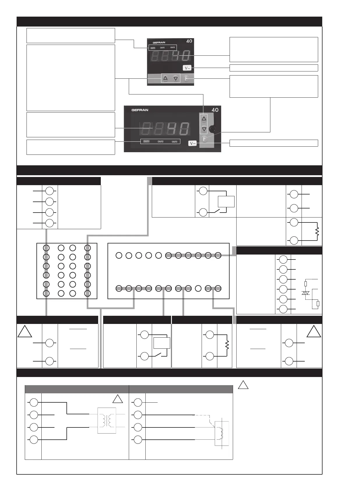
Generic user-
configurable outputs
- relay 5A/250Vac
- logic 6V/20mA,
(Rout = 220Ω)
- Triac
20...240Vac ±10%
3A max
• Outputs
12
14
13
15
Out3
-
+
Out2
16
17
-
+
Out1
~
~
Line
Load
TRIAC
!
Generic user-
configurable output
4 to 20mA, Rmax. 150Ω
Generic user-
configurable output
- relay 5A/250Vac
Out3
Isolated digital input
1500V
Ri = 5,6KΩ
(24V, 4mA)
6
5
+
-
External
supply
6
5
6
5
+
-
R
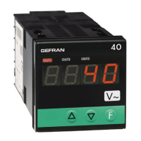
“Raise” and “Lower” keys:
These keys are used for any operation that
requires a numerical parameter to be raised or
lowered. ••The speed of change is proportional
to the time the key is pressed. •• The operation
is not cyclic: once the maximum (minimum) limit
is reached, there will be no further increase
(decrease) of the value, even if the key remains
pressed.
The keys can be configured to perform
reset, hold, display of the peak value, etc. as
determined by the ‘t.U.’ and ‘t.d.’ parameters on
the ‘In’ menu.
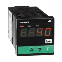
3 • DESCRIPTION OF FACEPLATE
PV display: Indication of process variable ••
Indication of ‘HI’ or ‘Lo’ out of range •• IIndication
of off scale beyond the limits of positive calibration
(br) and negative (Er) •• Display of configuration
and calibration messages
Function key:
Gives access to different configuration stages ••
Confirms any parameter changesi
Label with engineering units
Indication of output states:
OUT 1 (Alarm 1); OUT 2 (Alarm 2);
OUT 3 (Alarm 3)
Standard:
100 to 240Vac/dc
±10%
Optional:
11 to 27Vac/dc ±10%
50/60Hz
6
5
4
3
2
1
7
8
9
10
11
12
18
17
16
15
14
13
19
20
21
22
23
24
• Power supply
11
10
~
~
!
• Logic input / Retransmission output / Relay output
• Inputs
PWR
Indication of output states:
OUT 1 (Alarm 1); OUT 2 (Alarm 2);
OUT 3 (Alarm 3)
114 5 1083 972 61
1219 18 131520 141621 1722
Standard:
100 to 240Vac
±10%
Optional:
20 to 27Vac/dc ±10%
50/60Hz
• Power supply
23
24
~
~
PWR
!
Label with engineering units
• Outputs
Generic user-
configurable outputs
- relay 5A/250Vac
- logic 6V/20mA,
Rout = 220Ω
19
21
20
22
-
+
Out2
-
+
Out1
4 • CONNECTIONS
Digital
input 1500V
isolation
Ri = 5,6KΩ
(24V, 4mA)
6
5
+
-
• Logic Input
Analog
retransmission
output
4...20mA,
Rmax. 150Ω
8
7
+
-
• Retransmis. output
• AC current input (A~)
4
2
3
1
IN
COM
20mAac, 50mAac, 200mAac
4
2
3
1
• AC voltage input (V~)
IN
1Aac, 5Aac
2Vac, 20Vac, 200Vac, 500Vac
V~
ATTENTION: Terminals 2 and 3 are connected to terminal 1 at
low impedance
ATTENTION:
- Analog retransmission output option:
negative reference is connected
electrically to terminal 1.
- Logic output:
negative reference is connected
electrically to terminal 1.
- Connection of the input directly to high
voltage (200Vac, 500Vac) requires relay-
type outputs without retransmission only;
otherwise, you have to use a transformer
with double isolation with maximum
secondary voltage of 20Vac
R
External
supply
PV display: Indication of process variable••
Indication of ‘HI’ or ‘Lo’ out of range •• Indication
of off scale beyond the limits of positive calibration
(br) and negative (Er) •• Display of configuration
and calibration messages
!
2
81661G_MHW_40A48-96_09-2016_ENG
 Loading...