Max. non-linearity error See t.P parameter at page 3
For correct and safe
installation, follow the
instructions and
observe the warnings
contained in this
manual.
Faceplate protection IP65
Working / Storage temperatures 0...50°C / -20...70°C
Relative humidity 20 to 85%, non-condensing
Installation Panel mounting
Weight 90g for the complete version
Resolution
(function of settable sample time)
120msec, >13bit - 8000 points
60msec, >13bit - 8000 points (only for linear inputs)
30msec, >12bit - 4000 points (only for linear inputs)
15msec, >11bit - 2000 points (only for linear inputs)
Thermocouples
J, K, R, S, T, B, E, N
(IEC 584-1, CEI EN 60584-1, 60584-2)
L GOST, U, G, D, C
Custom linearization available on request
Cold junction error 0,1° / °C
RTD type (scale configurable within indicated
range, with or without decimal point)
Max. RTD line resistance
DIN 43760 (PT100), JPT100
20Ω
PTC type / NTC type 990Ω, 25°C / 1KΩ, 25°C
°C / °F selection Faceplate configurable
Linear scale ranges
-1999 to 9999 (with 4 digit display)
-999 to 999 (with 3 digit display)
-99 to 99 (with 2 digit display)
Configurable decimal point position, possible 32
segment linearization
(option) Power supply for 2-
wire transmitter
18V ±10%, 30 mA
1.2 V DC for potentiometer > 100 Ω (version P77)
Power supply (switching)
11...27 V DC, 18...27VAC ±10%,
50/60Hz, 3VA (not isolated)
Display
2, 3, 4 digits, red, height 14 mm
Keys 3 mechanical keys (Raise, Lower, F)
Accuracy
0.2% f.s. at 25°C ambient temperature, ts=120msec
Main input
TC, RTD, PTC, NTC
60 mV, 1 V, 5 V, 10 V, Ri ≥ 500KΩ
20 mA, Ri = 50Ω
adjustable digital filter
1 • INSTALLATION
• Dimensions and cut-out: Panel mounting
Panel mounting:
Fix the device with the bracket provided before making any electrical connections.
To mount two or more devices side by side, use the cut-out dimensions shown above.
CE MARKING: The instrument conforms to the European Directives 2004/108/CE and
2006/95/CE with reference to the generic standards:
EN 61000-6-2 (immunity in industrial
environment)
EN 61000-6-3 (emission in residential environment) EN 61010-1 (safety).
MAINTENANCE: Repairs must be done out only by trained and specialized personnel.
Cut power to the device before accessing internal parts.
Do not clean the case with hydrocarbon-based solvents (Petrol, Trichlorethylene, etc.).
Use of these solvents can reduce the mechanical reliability of the device. Use a cloth
dampened in ethyl alcohol or water to clean the external plastic case.
SERVICE: GEFRAN has a service department. The warranty excludes defects caused
by any use not conforming to these instructions.
2 • TECHNICAL SPECIFICATIONS
FUNCTION CABLE LENGTH USED
TC input probe 0,8 mm
2
compensated 5 mt
“PT100” input probe 1 mm
2
3 mt
Power supply cable 1 mm
2
1 mt
EMC conformity has been tested with the following connections
!
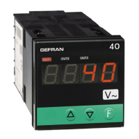
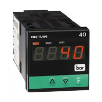
4T 72
UNIVERSAL TEMPERATURE INDICATOR
SOFTWARE VERSION 1.0x / 2.0x
code 81606B / edition 06 - 06/09
USER’S MANUAL
1
81606B_MHW_4T72_0609_ENG