Do you have a question about the gefran 650 L and is the answer not in the manual?
Describes the general characteristics and functions of the 650 L and 1250 L indicators.
Details physical and functional distinctions between the 650 L and 1250 L models.
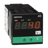
Provides an overview of the 650 L indicator's features, display, and keys.
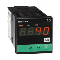
Details the 1250 L indicator's features, display, and keys.
Covers general considerations, dimensions, and panel fastening for device installation.
Explains general considerations, EMC, cables, power supply, and I/O connections.
Illustrates terminal connections for the 650 L model, including options.
Shows terminal connections for the 1250 L model, including options.
Explains indicator displays, menu navigation, and key functions.
Details the indicator's self-diagnostics and startup sequence.
Guides through initial setup and fast configuration after first power-on.
Describes the process for quickly configuring the indicator's main functions.
Accesses detailed indicator settings via menus and passwords.
Provides an overview of the indicator's main menu structure and navigation.
Displays software version, serial address, and other system information.
Configures sensor type, linearization, units, and filters for the primary input.
Sets alarm parameters like type, hysteresis, delay, and messages.
Configures the type, state, and function of digital inputs.
Configures relay, logic, and triac outputs, including functions and messages.
Sets the indicator's operating mode and digital input types.
Configures Modbus RTU serial communication parameters.
Customizes display settings like bargraph, language, and scrolling speed.
Allows user calibration for inputs, outputs, and factory calibration reset.
Manages user access levels and factory reset procedures.
Illustrates a typical temperature control application with TC input and alarm relay.
Step-by-step guide for initial setup of a specific 650 L model.
Explains how to correct sensor readings using a 4-point linearization method.
Explains different types of generic alarms (absolute, deviation, symmetrical).
Details the physical connection and software requirements for PC configuration.
Introduces the GF_eXpress software for configuration and firmware updates.
Overview of the indicator's displays and front panel keys.
Describes the indicator's startup process and error handling.
Explains how to use the device as a standard indicator.
Lists common error messages and their meanings for troubleshooting.
Explains how to access and modify user-configurable parameters.
Procedure for replacing the indicator unit in the panel.
Instructions for replacing the gasket to maintain panel seal and IP protection.
Guidance on cleaning the indicator's exterior and interior components.
Information on the proper disposal of the indicator according to regulations.
Specifications for the display, lighting, bargraph, and keypad.
Details sensor types, accuracy, sampling time, and input signal specifications.
Describes relay, analog retransmission output specifications and capabilities.
Specifies operating voltage, power dissipation, and connection details.
Provides physical dimensions and weight for both indicator models.
Details compliance with EMC directives and standards.
Lists available 650 L models based on power supply and configuration options.
Lists available 1250 L models based on power supply and configuration options.
USB-TTL cable for PC programming and configuration.
Includes the GF_eXpress software for indicator configuration.
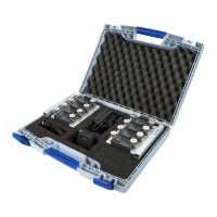
Kit for configuring new instruments.
Replacement gaskets for maintaining panel seal and IP protection.
Components used to secure the indicator in the panel.
Covers designed to enhance safety for terminal connections.
Spare terminals for the indicator's connection board.
| Brand | gefran |
|---|---|
| Model | 650 L |
| Category | Measuring Instruments |
| Language | English |