Do you have a question about the gefran 40B 48 and is the answer not in the manual?
Physical dimensions and panel cut-out details for mounting the device.
Electromagnetic compatibility and low voltage directive conformity details.
Guidelines for maintenance and cleaning, emphasizing safety and authorized personnel.
Information on the LED display type, digit count, height, and mechanical keys.
Details on accuracy, resolution, main input types (strain-gauge, potentiometer), and scale ranges.
Specifications for alarms, alarm masking, relay, logic, triac, and analog retransmission outputs.
Details on device power supply, sensor power, faceplate protection, temperature, and humidity.
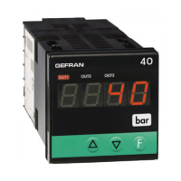
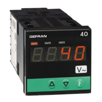
Details the indications shown on the PV (Process Variable) display and output states.
Explains the function of the Raise/Lower keys and the main Function key for navigation.
Details the connections for generic configurable outputs, relay, and logic outputs.
Wiring diagrams for logic input, retransmission output, and relay outputs.
Wiring diagrams for the standard and optional power supply connections.
Wiring diagrams for potentiometer and 4-wire strain-gauge inputs.
Wiring details for 6-wire strain gauge sensors, specific to SW2.0x.
Overview of the main display and navigation path for programming.
How to access and view information like software version and CPU type.
Focuses on setting hysteresis parameters for alarm set points.
Configuration of probe type, signal, scale, and sampling time.
Options for digital input functions like hold, flash, and peak display.
Setting low and high limits for alarms and analog output.
Configuration of output parameters, number of outputs, and alarm types.
Setting digital filters for input, configuring decimal point, scale limits, and offset.
Defining the device's response to a damaged sensor.
Setting the protection code to control parameter modifiability.
Enabling and configuring custom linearization for the main input.
Performing user calibration for analog retransmission and sensor inputs.
Explains the Eb function for detecting probe power supply interruptions.
Describes how input values and alarms behave during Hold and Flash functions.
Illustrates normal/symmetrical absolute and deviation alarms with hysteresis.
Diagrams illustrating output filter behavior based on F.0 parameter.
Step-by-step calibration for strain-gauge with positive and negative polarization.
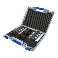
Information about the PC configuration cable and software.
Explanation of the order code structure for device configuration.
Detailed breakdown of order code options for the 40B 48 and 40B 96 models.
Crucial safety warnings for installation, connection, and usage.
Specific warnings related to device installation, wiring, and environmental considerations.
| Brand | gefran |
|---|---|
| Model | 40B 48 |
| Category | Measuring Instruments |
| Language | English |