EasyManua.ls Logo

gefran 40A 48 - User Manual

gefran 40A 48
8 pages
Print Icon
To Next Page IconTo Next Page
Loading...
99
10
45
45
48
70
70
63
48
105
10
108
96
48
44,5
92
70
115
Triac output
(option, only for 96 format)
20...240Vac ±10%, 3A max
Snubberless, inductive and resistive load I
2
t = 128A
2
S
Logic output
Main input
2Vac, 20Vac, 200Vac, 500Vac, Ri ≥ 1MΩ
Max. continuous voltage = 600Vac
Max. voltage for 1 minute = 900Vac
Voltage pulse 1,2/50ms = 2Kvpeak
20mAac, 50mAac, 200mAac, Ri = 1,6Ω
Max. continuous current = 400mAac at 50°C
1Aac, 5Aac, Ri = 16mΩ
Max. continuous current = 5.5Aac at 50°C
Max. frequency = 60Hz
For correct and safe
installation, follow the
instructions and observe
the warnings contained
in this manual.
1 • INSTALLATION
Dimensions and cut-out: Panel mounting
Panel mounting:
Fix the device with the bracket provided before making any electrical connections.
To mount two or more devices side by side, use the cut-out dimensions shown above.
CE MARKING: EMC (electromagnetic compatibility): conforms to directive 2014/30/EU
with reference to standard EN61326-1
Safety LVD: conforms to directive 2014/35/EU with reference to standard EN 61010-1
MAINTENANCE: Repairs must be done out only by trained and specialized personnel.
Cut power to the device before accessing internal parts.
Do not clean the case with hydrocarbon-based solvents (Petrol, Trichlorethylene, etc.).
Use of these solvents can reduce the mechanical reliability of the device.
Use a cloth dampened in ethyl alcohol or water to clean the external plastic case.
SERVICE: GEFRAN has a service department. The warranty excludes defects caused
by any use not conforming to these instructions.
2 • TECHNICAL SPECIFICATIONS
!
40A 48 / 40A 96
ALTERNATING CURRENT/VOLTAGE INDICATOR - INTERCEPTOR
SOFTWARE VERSION 1.0x / 2.0x
code 81661G / edition 10 - 09/2016
USER’S MANUAL
Faceplate protection IP65
Working / Storage temperatures 0 to 50°C / -20 to 70°C
Relative humidity 20 to 85%, non-condensing
Installation Panel mounting, extractable from front
Weight
160g (mod. 48); 320g (mod. 96) for the complete version
Resolution >13bit - 8000 points
Linear scale ranges
-1999 to 9999 (with 4 digit display)
-999 to 999 (with 3 digit display - only for model 96)
Configurable decimal point position
Alarms (set points)
Maximum of three configurable alarms:
absolute, deviation, symmetrical deviation.
Adjustable hysteresis
Alarm masking
- exclude on power-up
- latch reset from key and/or external contact
- insert delay filter (DON, DBI, DOF, DPO)
- set minimum intervention time
Relay contact NO (NC) 5A, 250V
11VDC, Rout = 220 Ω (6V/20mA)
Fault settings
Alarm states can be configured in probe fault
condition
Analog retransmission (option) 4 to 20mA, max. 150 Ω load
Logic input Ri=5.6KΩ (24v, 4mA), 1500 V isolation
Logic input functions
configurable for alarm memory reset, hold, flash,
zero, selection of max., min. peak value, peak-peak
Fuse (inside device, not
operator serviceable)
100 to 240Vac/dc - type T - 500mA - 250V
11 to 27Vac/dc - type T - 1.25A - 250V
Power supply (switching)
40A 48 (standard) 100...240Vac ±10% - 8VA
(optional) 20...27Vac/dc ±10% - 8VA
40A 96 (standard) 100...240Vac/dc ±10% - 7,5VA
(optional) 11...27Vac/dc ±10% - 5VA
50/60Hz
Display
3, 4 digit red LED’s
mod. 48 digit height 10mm (4 digits)
mod. 96 digit height 20mm (3 digits),
digit height 14mm (4 digits)
Keys 3 mechanical keys (Raise, Lower, F)
Accuracy
0.2% f.s. for 2 Vac, 20 Vac, 20mAac inputs
50mAac, 1Aac, at room temperature of 25° C
0.5% f.s. for 200Vac, 500Vac, 200mAac, 5Aac
inputs, values shown are for max. rms value with
sine wave signal
Environmental conditions of use for internal use only, altitude up to 2000m
1
81661G_MHW_40A48-96_09-2016_ENG
Question and Answer IconNeed help?

Do you have a question about the gefran 40A 48 and is the answer not in the manual?

Summary

Installation

Dimensions and Cut-out: Panel Mounting

Provides dimensions for panel mounting and cut-out, including diagrams for device placement.

Technical Specifications

Description of Faceplate

Faceplate Components Overview

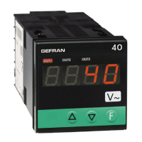
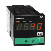
Details key components of the faceplate including display, keys, and indicator states.

Connections

Output Connections

Details configuration for relay and logic outputs, including terminal assignments.

Logic Input and Retransmission Output

Explains connections for digital logic input and analog retransmission output.

Power Supply Connections

Outlines connections for standard and optional power supply inputs.

Input Signal Connections

Details connections for AC voltage and AC current input signals.

Programming and Configuration

Level 1 Display Navigation

Describes initial display and navigation to parameters like PV, Setpoints, and functions.

Information Display Parameters

Details parameters for software version, CPU type, and input/output scale limits.

Configuration Parameters

Covers settings for hysteresis, digital input function, and key functions.

Input and Output Parameter Settings

Defines settings for AC input types and alarm types for outputs.

Alarms

Alarm Types and Behavior

Explains normal absolute, deviation, and symmetrical alarm types with diagrams.

Output Filtering Options

Illustrates output behavior with filtering parameters F.0 (DON, DBI, DOF, DPO).

Accessories

Current Transformers

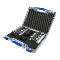
Details current transformers for measuring current, including specifications and order codes.

RS232 Interface Cable

Describes the interface cable for PC configuration and its usage.

Order Code Configuration

Device Configuration Options

Explains how to select digits, outputs, power supply, and input/retransmission options.

General Safety Warnings

Installation and Usage Precautions

Provides critical safety warnings regarding installation, wiring, and device operation.

Overview

The Gefran 40A 48/40A 96 is an alternating current/voltage indicator and interceptor, designed for panel mounting. It provides clear visual feedback through LED displays and offers extensive configuration options to suit various industrial applications.

Function Description:

This device serves as a precise indicator for AC voltage and current, with the ability to intercept and manage alarms based on configurable setpoints. It can display process variables, alarm states, and configuration messages. The indicator supports various input types, including AC voltage (2V, 20V, 200V, 500V) and AC current (20mA, 50mA, 200mA, 1A, 5A), making it versatile for different measurement needs. It features up to three configurable alarms, which can be set as absolute, deviation, or symmetrical deviation types, with adjustable hysteresis. The device also includes logic inputs for functions like alarm memory reset, hold, flash, zero, and peak value selection, as well as relay, logic, and triac outputs for control. An optional analog retransmission output (4-20mA) is available for integration into other control systems.

Important Technical Specifications:

  • Display:
    • 40A 48: 4-digit red LED, 10mm digit height.
    • 40A 96: 3-digit red LED, 20mm digit height; 4-digit red LED, 14mm digit height.
  • Keys: 3 mechanical keys (Raise, Lower, F) for navigation and parameter adjustment.
  • Accuracy:
    • 0.2% f.s. for 2 Vac, 20 Vac, 20mAac, 50mAac, 1Aac inputs at 25°C.
    • 0.5% f.s. for 200Vac, 500Vac, 200mAac, 5Aac inputs.
    • Values shown are for max. RMS value with sine wave signal.
  • Resolution: >13bit - 8000 points.
  • Main Input:
    • Voltage: 2Vac, 20Vac, 200Vac, 500Vac (Ri ≥ 1MΩ). Max continuous voltage = 600Vac. Max voltage for 1 minute = 900Vac. Voltage pulse 1.2/50ms = 2Kvpeak.
    • Current: 20mAac, 50mAac, 200mAac (Ri = 1.6Ω). Max continuous current = 400mAac at 50°C.
    • Current: 1Aac, 5Aac (Ri = 16mΩ). Max continuous current = 5.5Aac at 50°C.
    • Max frequency = 60Hz.
  • Linear Scale Ranges: -1999 to 9999 (4-digit display); -999 to 999 (3-digit display for model 96). Configurable decimal point position.
  • Alarms: Up to three configurable alarms (absolute, deviation, symmetrical deviation) with adjustable hysteresis. Alarm masking options include power-up exclusion, latch reset (from key and/or external contact), and insert delay filter.
  • Relay Contact: NO (NC) 5A, 250V.
  • Logic Output: 11VDC, Rout = 220 Ω (6V/20mA).
  • Triac Output (option, 96 format only): 20-240Vac ±10%, 3A max. Snubberless, inductive and resistive load It = 128A²S.
  • Analog Retransmission (option): 4 to 20mA, max. 150 Ω load.
  • Logic Input: Ri=5.6KΩ (24V, 4mA), 1500 V isolation. Configurable for alarm memory reset, hold, flash, zero, selection of max., min. peak value, peak-peak.
  • Power Supply (switching):
    • 40A 48: Standard 100-240Vac ±10% - 8VA; Optional 20-27Vac/dc ±10% - 8VA.
    • 40A 96: Standard 100-240Vac/dc ±10% - 7.5VA; Optional 11-27Vac/dc ±10% - 5VA.
    • 50/60Hz.
  • Fuse (inside device, not operator serviceable): 100-240Vac/dc: type T-500mA - 250V; 11-27Vac/dc: type T-1.25A - 250V.
  • Faceplate Protection: IP65.
  • Working/Storage Temperatures: 0 to 50°C / -20 to 70°C.
  • Relative Humidity: 20 to 85%, non-condensing.
  • Environmental Conditions of Use: For internal use only, altitude up to 2000m.
  • Installation: Panel mounting, extractable from front.
  • Weight: 160g (mod. 48); 320g (mod. 96) for the complete version.
  • CE Marking: EMC (2014/30/EU, EN61326-1); Safety LVD (2014/35/EU, EN 61010-1).

Usage Features:

The device offers a user-friendly interface with a clear LED display and three mechanical keys for programming and configuration. Parameters can be adjusted for various functions, including decimal point position, input scale limits, offset correction, hysteresis for setpoints, digital input functions (e.g., hold, flash, peak display, alarm reset), and output settings (alarm type, filter modes). The "F" key provides access to different configuration stages and confirms parameter changes. The "Raise" and "Lower" keys facilitate numerical parameter adjustments, with speed proportional to the key press duration.

Special functions like "HOLD" and "FLASH" enhance operational flexibility. In "HOLD" mode, the input value and alarms are frozen when the logic input is active, and a reset turns off relay outputs and alarm latches. In "FLASH" mode, the input value is sampled, alarm states are not transferred to outputs, and outputs are "frozen," but updated according to calculated alarm states when the logic input is active.

The device supports current transformers for measuring higher currents, with various models available for different primary current ratings (25A to 50A) and secondary outputs (2Vac or 4Vac). An optional RS323 interface cable and programming software are available for PC-based configuration.

Maintenance Features:

Maintenance and repairs should only be performed by trained and specialized personnel. It is crucial to cut power to the device before accessing internal parts. The case should not be cleaned with hydrocarbon-based solvents (e.g., Petrol, Trichlorethylene) as these can reduce mechanical reliability. Instead, a cloth dampened in ethyl alcohol or water should be used to clean the external plastic case. The manual emphasizes that the warranty excludes defects caused by any use not conforming to the provided instructions.

Safety Warnings:

The manual includes critical warnings for installation, connection, and use. It highlights the importance of using suitable cables, ensuring proper grounding, and separating power supply lines from input/output lines. The device does not have an ON/OFF switch and powers on immediately when connected. For safety, a two-phase disconnecting switch with proper marking, easily reachable by the user, is required for permanently connected devices. The device should not be used in inflammable or explosive environments unless suitable interfaces are employed. It contains components sensitive to static electrical discharges, requiring appropriate precautions during handling. The equipment is intended for permanent indoor installations within an enclosure or panel. It is crucial to avoid dust, humidity, corrosive gases, and heat sources, and to ensure proper ventilation. The manual also provides detailed guidelines for input and output connections, including the use of twisted and screened cables for analog inputs and RC groups for inductive loads.

gefran 40A 48 Specifications

General IconGeneral
Brandgefran
Model40A 48
CategoryMeasuring Instruments
LanguageEnglish

Related product manuals