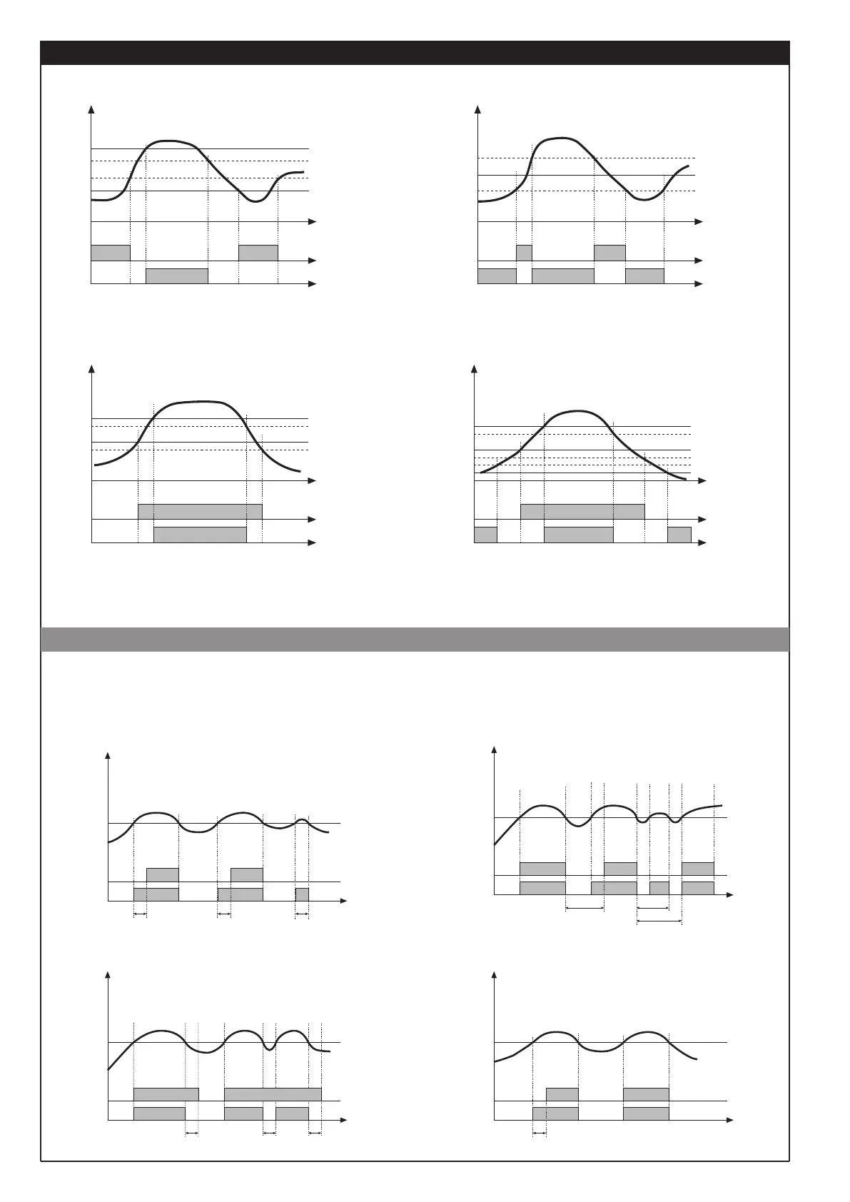
6 • ALARMS
tempo
AL1 + H1
AL2 + H2
AL2
AL1
alarm 1
alarm 2
(*)
For AL1 inverse absolute alarm (min.) with positive H1, 1 t = 1
(*) = OFF if disabling on power-on exists
For AL2 direct absolute alarm (max) with negative H2, 2 t = 0
For AL1 inverse absolute, symmetrical alarm with hysteresis H1, 1 t = 5
For AL1 direct absolute, symmetrical alarm with hysteresis H1, 1 t = 4
Normal absolute alarm Symmetrical absolute alarm
inverse
direct
AL1
AL1 + [ H1 ]
AL1 - [ H1 ]
tempo
For AL1 direct absolute alarm (max) with negative H 1, 1 t = 0
For AL2 direct relative alarm (max) with negative H2, 2 t = 2
For AL1 direct absolute alarm (max) with negative H1, 1 t = 0
For AL2 symmetrical deviation alarm H2, 2 t = 6
tempo
AL1+AL2
AL1
alarm 1
alarm 2
AL1+AL2
AL1
alarm 1
alarm 2
tempo
AL1 + AL2 + H2
Normal deviation alarm
(AL1 absolute, AL2 relative)
Symmetrical deviation alarm
(AL1 absolute, AL2 relative)
AL1-AL2
AL1 + H1
AL1+AL2+H2
AL1+H1
time
Alarm
setpoint
Output
Alarm
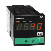
F.0 = 1
DON = Delayed activation
F.0 = 2
DBI = Delay in turning on output after output is
turned off
time
time
time
F.0 = 3
DOF = Delayed deactivation
F.0 = 4
DP0 = Delayed activation only at power-on
Variable
rA rA
t < rA
Alarm
setpoint
Output
Alarm
Variable
rA
t < rA
t > rA
Alarm
setpoint
Output
Alarm
Variable
Alarm
setpoint
Output
Alarm
Variable
rA
rA rA
rA
The diagrams refer to a normal absolute alarm with hysteresis H = 0
• Filter - outputs with reference to parameters F.0 and r.A
6
81661G_MHW_40A48-96_09-2016_ENG