TRAFO 1 TRAFO 5
WSK-0-0-0
Interface cables
+ CD Winstrum
• ORDER CODE
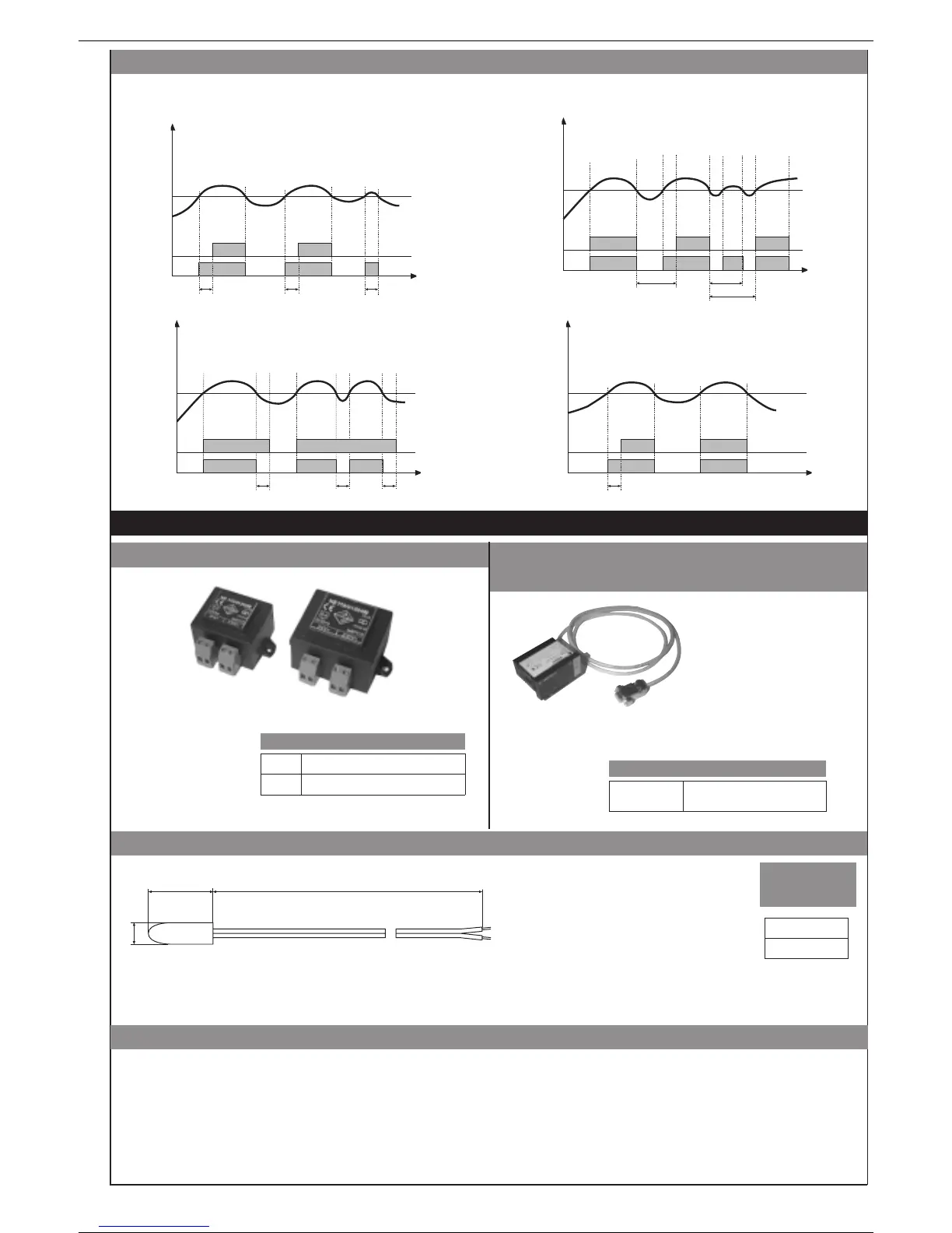
time
Alarm
setpoint
Output
Alarm
F.0 = 1
DON = Delayed activation
F.0 = 2
DBI = Delay in turning on output after output is
turned off
time
time
time
F.0 = 3
DOF = Delayed deactivation
F.0 = 4
DP0 = Delayed activation
only at power-on
Variable
rA rA
t < rA
Alarm
setpoint
Output
Alarm
Variable
rA
t < rA
t > rA
Alarm
setpoint
Output
Alarm
Variable
Alarm
setpoint
Output
Alarm
Variable
rA
rA rA
rA
The diagrams refer to a normal absolute alarm with hysteresis H = 0
• Filter - outputs with reference to parameters F.0 and r.A
TRAFO 5
10VA, 230/24Vac transformer
TRAFO 1
3VA, 230/24Vac transformer
NTC
• PTC / NTC
• Transformer
• RS323 interface cable for
configuration
7 • ACCESSORIES
25 ±1
Ø 7 ±0,5
5,50m
PTC 7 x 25 5m
• ORDER
CODE
TECHNICAL DATA
Mod. probe: Ambient probe
Cap material: Plastic (Ø 7 x 25mm)
Temperature range: -20...80°C
PTC: R 25°C = 1KΩ ±1%
(KTY 81-110)
Response time: 20sec (in still air)
Isolation: 100MΩ, 500Vdc
between cap and terminals
Wire material: Unipolar in PVC (12/0,18)
Wire length: 5,50m
• ORDER CODE
Conform to VDE 0551, EN 60742, CE
TRAFO 5:
L: 51,5mm,
B: 52,5mm,
H: 35mm
TRAFO 1:
L: 44,5mm,
B: 46,2mm,
H: 32,5mm
Size
N.B.:
the PC configuration
cable is supplied with the
programming software.
Make the connection with
the device powered and
with inputs and outputs
disconnected.
• Installation notes
Always power the devices by means of the TRAFO1 transformers specified in the manual (one for each device) when:
• The application is unknown.
• Multiple devices have input signals that are not isolated from one another, such as, for example: non-isolated grounded thermocouples, transducers or transmitters
powered by a single supply, linear inputs with voltage or current not isolated from one another.
• It is a general rule that devices with shared signals (probes, transmitters, signal retransmission, etc.) must be powered by a separate transformer for each device.
• Any special cases not covered by the above example must be evaluated from time to time.
• One possible example of a power supply by a single transformer is the case of devices with RTD or PTC probes, with relay or logic outputs connected to individually
isolated devices (such as GTS static groups).
ATTENTION: in case of an input with a NON-isolated grounded thermocouple, the secondary of the power transformer for the device CANNOT be grounded: doing so
will cause the device to fail, with probable blowing of the internal fuse.
5
81606B_MHW_4T72_0609_ENG
 Loading...