EasyManuals Logo

gefran ADV200 Quick Start Up Guide

gefran ADV200
20 pages
To Next Page IconTo Next Page
To Previous Page IconTo Previous Page
Page #18 background imageLoading...
Page #18 background image
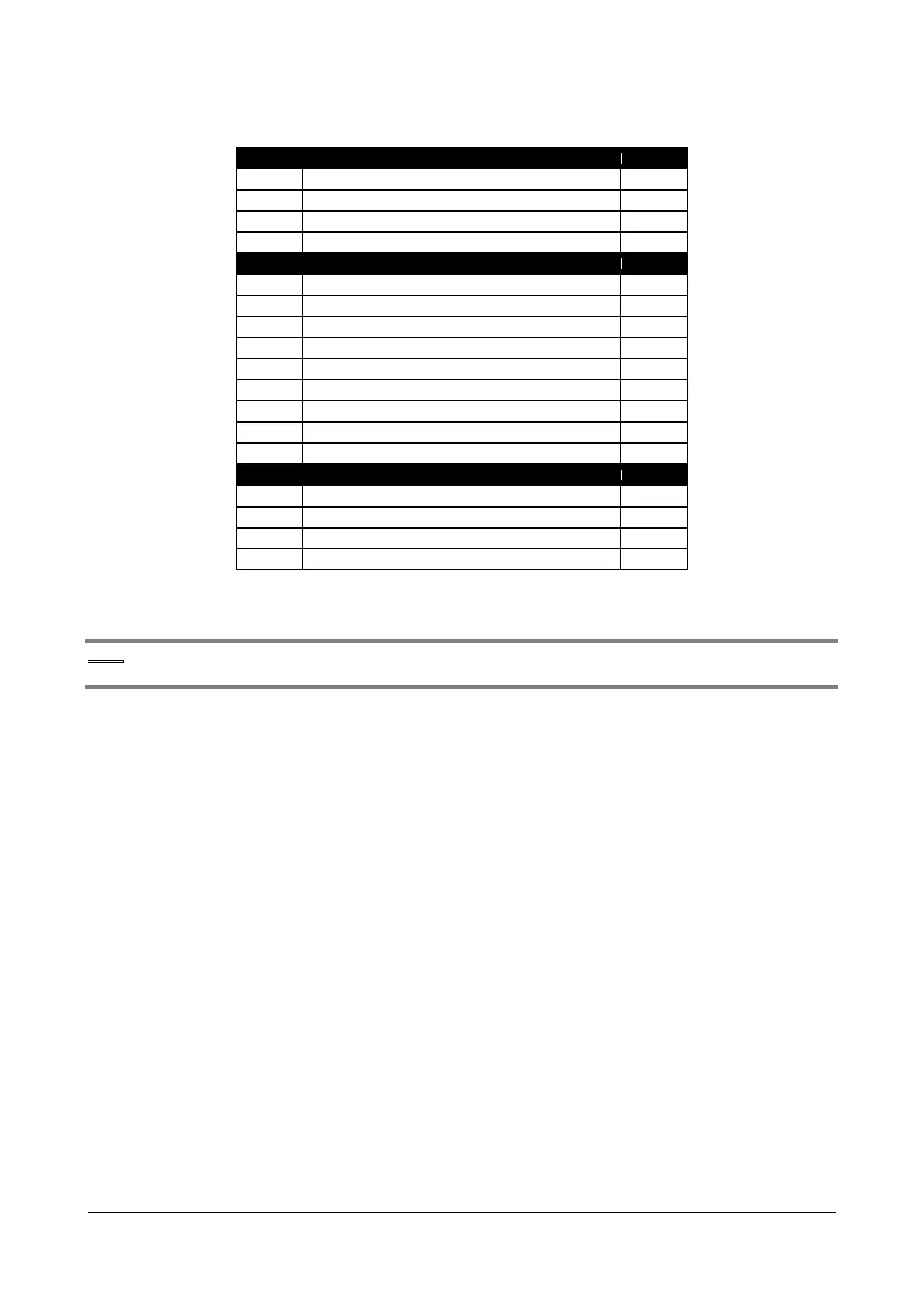
5.2.5.5 Led scheda R-PSM
LED
Funzione “MONITOR”
Colore
D9
Alimentazione logica +3V3
VERDE
D78
Alimentazione logica +5V
VERDE
D79
Alimentazione driver +22V
VERDE
D91
Presenza Tensione DC-Link
BLUE
LED
Funzione “SEGNALAZIONE
Colore
D1
Tensione DC-Link sopra soglia UNDERVOLTAGE
VERDE
D2
Alimentatore abilitato
VERDE
D3
Non Usato
VERDE
D4
Alimentatore OK (assenza allarmi escluso UV)
VERDE
D6
Allarme Mancanza fase o Mancanza rete
ROSSO
D7
Allarme sovratemperatura dissipatore
ROSSO
D8
Configurazione FPGA in corso
VERDE
D84
Allarme frequenza di rete errata
ROSSO
J3 – J5
Cavo sincronizzazione tra J3 master e J5 SLAVE inserito
GIALLO
LED
Funzione STATO ALIMENTATORE
Colore
D83
Bit S0: codifica lo STATO dell’alimentatore (LSB)
GIALLO
D80
Bit S1: codifica lo STATO dell’alimentatore
GIALLO
D81
Bit S2: codifica lo STATO dell’alimentatore (MSB)
GIALLO
D82
Ponte SCR bridge abilitato
GIALLO
Note!
Per la posizione dei Jumper vedere la “Figura 5.2.5.1: Posizione Switches, Led e Jumper sulla scheda
R-PSM”.
Addendum to the ADV200 / ADV200WA QS Instruction books Page 18 of 20

Other manuals for gefran ADV200

Questions and Answers:

Question and Answer IconNeed help?

Do you have a question about the gefran ADV200 and is the answer not in the manual?

gefran ADV200 Specifications

General IconGeneral
Brandgefran
ModelADV200
CategoryInverter
LanguageEnglish

Related product manuals