An incorrect mains frequency setting will block the control card: the mains frequency tolerance is ±5%.
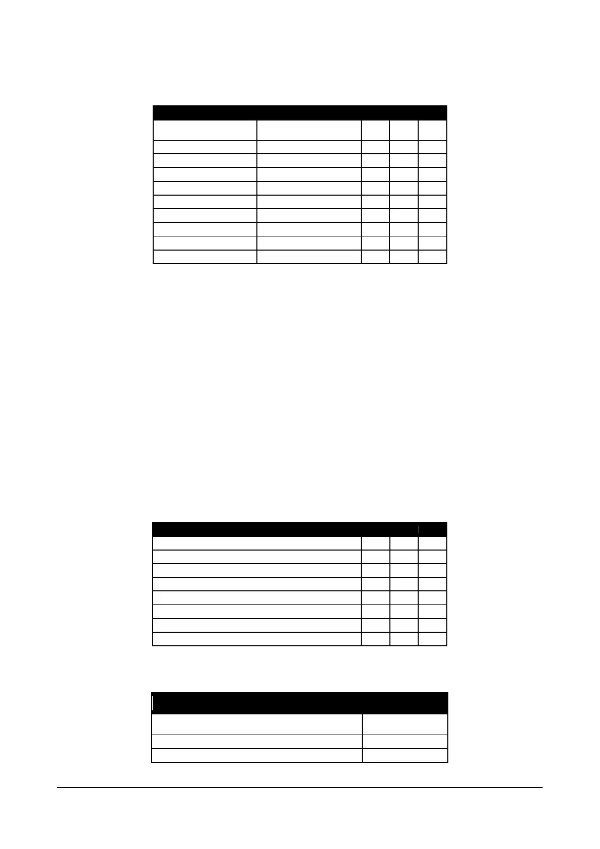
S2 - Precharge time configuration switches
Selection of pre-charge time
for 50Hz line
Selection of pre-charge time
for 60Hz line
S2-2 S2-3 S2-4
Switch S2-2…4 lets you set the pre-charge time for the capacitors connected to the DC link.
The default configuration calls for a time of 11.6[s] for a 50[Hz] line and 12.1[s] for a 60[Hz] line.
Remember that with equal levels of energy to be transferred to the condenser bank, decreasing the precharge time increases
the current draw.
The rectifier bridge and pre-charge inductance are sized for maximum peak current of 400[Apk]
Considering that with decreased pre-charge time the increased current is not linear, and that the larger the capacitors bank
connected to the DC Link the greater the energy to be transferred, if you need a pre-charge time shorter than the default
configuration you have to run the following check procedure:
1) Keep the default configuration of switches S2-2…4 and connect an current probe to output C or D of the ADV200 module.
The probe must be able to measure a peak current ≤ 10[ms].
2) Power and enable the pre-charge bridge by measuring the value of the peak current absorbed.
3) Cut power to the pre-charge bridge and wait for the DC Link to discharge completely (discharge time depends on the total
capacitance installed on the DC Link).
4) Set the switches to have a pre-charge time of 8.7[s] (8[s] for 60[Hz] line).
5) Repeat point 2). If the peak current measured is below 400[Apk] you can further reduce the pre-charge time. In this case,
run the entire procedure again until you reach the required pre-charge time.
S7-1…3 – Dig Out 2 configuration switch
No Mains Loss or Phase Loss (*) (**)
Drive OK ( excluded UV alarm)
The configurable output goes high when the condition indicated in the table occurs.
S7-4 -Function exchange between Relay 1 and Digital Out 2
Function S7-4
Function exchanged between Relay 1 and Digital Out 2
Addendum to the ADV200 / ADV200WA QS Instruction books Page 8 of 20

 Loading...


