www.gemu-group.com 27 / 76 GEMÜ 1436 cPos
13.6 Actual value output
Plug Pin Signal name Wiring
X2 1 I+, actual value out-
put
internal
external
0 - 20 mA /
4 - 20 mA
GND
2 I-, actual value out-
put
13.7 Relay outputs
Plug Pin Signal name Wiring
X1 2 Output K1
internal
external
+24 V DC
+24 V DC
GND
24 V DC voltage
24 V DC voltage
3 GND
4 Output K2
NOTICE
▶ The mode of operation of the outputs can be changed
over from NO (make contact) to NC (break contact) in the
3 SetFunction – K1 Switch/K2 Switch menu item.
13.8 Digital inputs
The product offers the option of using digital inputs for cer-
tain functions. It is also available to order with two exclusively
digital inputs.
In addition to this, it provides the option of using the analogue
actual value and set value input as a digital input under cer-
tain conditions as standard. The special wiring of the ana-
logue inputs in the following chapter only applies if the
product is delivered without an optional digital input card.
The option of two additional digital inputs describes "normal"
wiring of the inputs (see “Optional digital inputs“, page28).
On the Profinet, Profibus DP and DeviceNet fieldbus versions,
the digital input functions can be used in addition as standard
and do not need to be ordered separately.
The digital inputs facilitate the use of different functions to
control the positioner in addition to the analogue control sig-
nals.
- Up to four parameter sets with different settings (including
valve positions) can be stored and called up by two digital
inputs through a logical connective (ParmSet Bx function).
- The positioner can be stopped by the signal from a digital
input (automatic control system deactivated, current valve
position is maintained) or by moving the valve to the safety
position defined under ErrorAction (function OFF/ON or
Safe/On).
- The output source of the analogue actual value output can
also be controlled externally (function Poti/Ix).
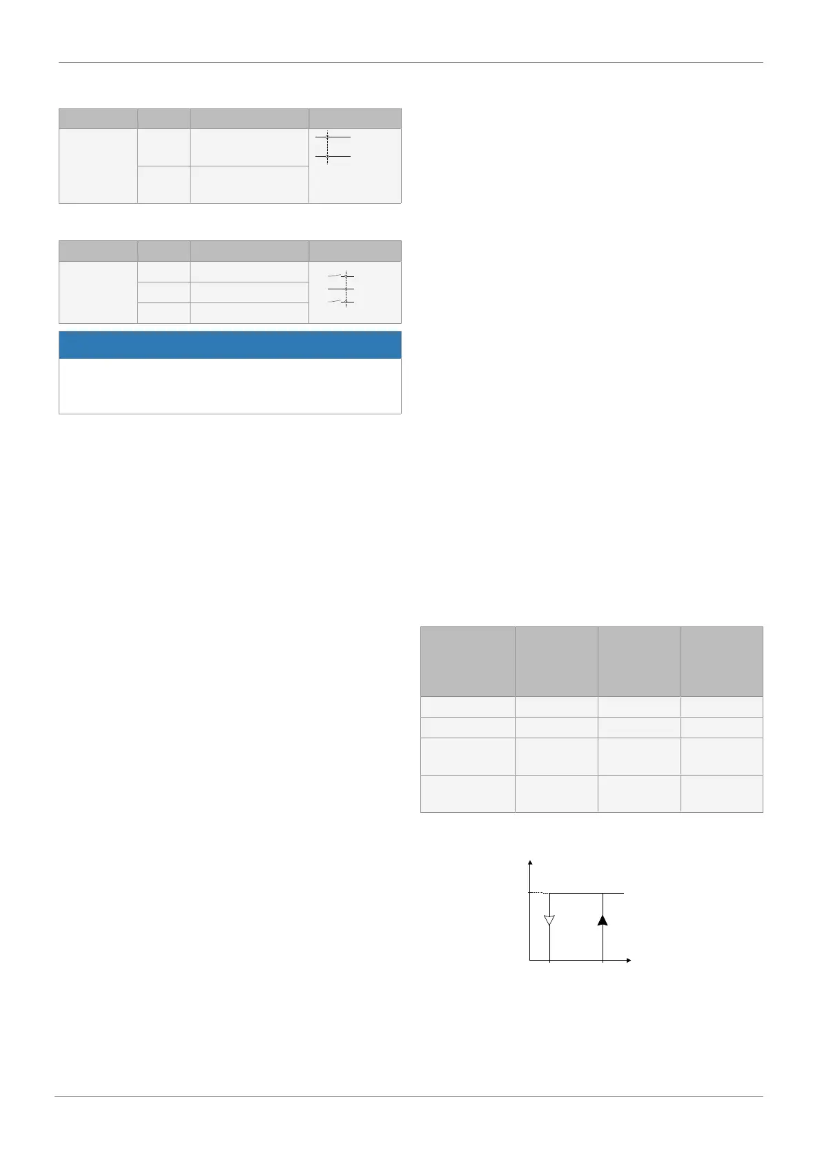
13.8.1 Use of actual value and set value inputs as digital inputs
The actual value and set value input can be used as a digital
input under the following conditions:
Control system Operating
mode
Set value in-
put as digital
input "in W"
Actual value
input as di-
gital input "in
X"
Positioner AUTO X
Positioner MANUAL X X
Process con-
troller
AUTO
Process con-
troller
MANUAL X
13 Electrical connection