www.gemu-group.com 57 / 76 GEMÜ 1436 cPos
Defines the permissible control deviation (dead zone)
between set value and actual value.
Effects both the positioner and the process controller.
NOTICE
▶ The level of the system deviation should always corres-
pond to the requirements of the valve and the control cir-
cuit. It is recommended that you do not set a value of <
1.0%, since this could cause oscillating control character-
istics (especially for actuators with discontinuous move-
ment profiles). This could put a great deal of stress on
the internal pilot valves and cause them to reach the end
of their service life more quickly.
▶ The following principle applies: The smaller the set value,
the greater the wear and the shorter the service life.
Therefore, the value should only be set to the exact value
required.
16.2.3.7.1.4 Setting the optional digital input parameters
Digital Input:
Submenu for setting the digital inputs.
- In W: Defines the functions of the High signal at digital input
InW (connection at set value input, only effective for
manual operation).
- In X: Defines the functions of the High signal at digital input
InX (connection at actual value input, only effective when
operating as a positioner).
- In 1: Defines the functions of the High signal at digital input
1.
- In 2: Defines the functions of the High signal at digital input
2.
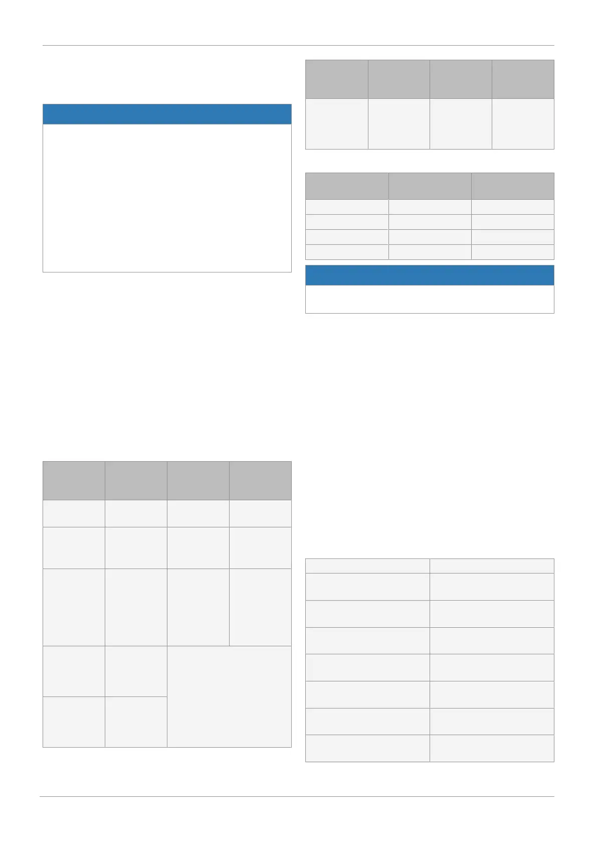
Parameters Function Function at
low signal
level
Function at
high signal
level
OFF Digital inputs
deactivated
OFF/ON Sets the posi-
tioner to the
pause mode
OFF:
Positioner in
pause mode
ON:
Positioner act-
ive
Safe/ON Moves the po-
sitioner into
the safety po-
sition
Safe:
Positioner
moves to the
position
defined under
Error Action
ON:
Positioner act-
ive
ParmSetB0 Loads para-
meter sets
into the work-
ing memory
See following table
ParmSetB1 Loads para-
meter sets
into the work-
ing memory
Parameters Function Function at
low signal
level
Function at
high signal
level
Poti / Ix Defines the
function of the
actual value
output
Poti:
Valve position
Ix:
Process ac-
tual value
Current signal for
ParmSetB1
Current signal for
ParmSetB0
Memory which is
read out
0 0 P1
0 1 P2
1 0 P3
1 1 P4
NOTICE
▶ Before loading another parameter set, this must be
loaded into the relevant memory.
If a digital input (In W, In X, In 1 or In 2) is set to the OFF / ON
or Safe / ON function and the digital signal "High" is not con-
nected, the following messages will be displayed:
- In 1 no Signal: The positioner moves to the safe position or
is stopped.
- In 2 no Signal: The positioner moves to the safe position or
is stopped.
- In W no Signal: The positioner moves to the safe position or
is stopped.
- In X no Signal: The positioner moves to the safe position or
is stopped.
16.2.3.7.1.5 Setting output functions and switch points
DigitalOutput:
Submenu for setting relay outputs K1 and K2.
- K1 Switch: Defines the output contact type.
NO – make contact or NC – break contact
- K1 fn: Determines the function of output K1.
(no) No function
(P min) Below the valve position pre-
set under AlarmMinK1
(P max) Above the valve position pre-
set under AlarmMaxK1
(P min/max) Above or below the preset
valve positions
(W min) Below the set value preset un-
der AlarmMinK1
(W max) Above the set value preset un-
der AlarmMaxK1
(W min/max) Above or below the preset set
value
(X min) Lower than the actual value
preset under AlarmMinK1
16 Operation