Cinterion
®
Connect Shield User Guide
2.2 Application / Arduino UNO Interface
18
connect_shield_ug_v01 2017-01-13
Confidential / Released
Page 8 of 19
2.2 Application / Arduino UNO Interface
The Cinterion
®
Connect Shield uses a few Arduino ONE interface signals, and it is possible to
combine the Connect Shield with other Arduino shields. To occupy as few signals as possible,
the Connect Shield output lines PWR_IND, RING, and CTS are connected to the Arduino in-
terface via output resistors, thus enabling these signals for a further usage, for example be-
tween the Arduino and another sensor shield. In this case the Arduino’s or sensor shield’s pin
drive strength must be higher than 5mA to overrule the Connect Shield’s output.
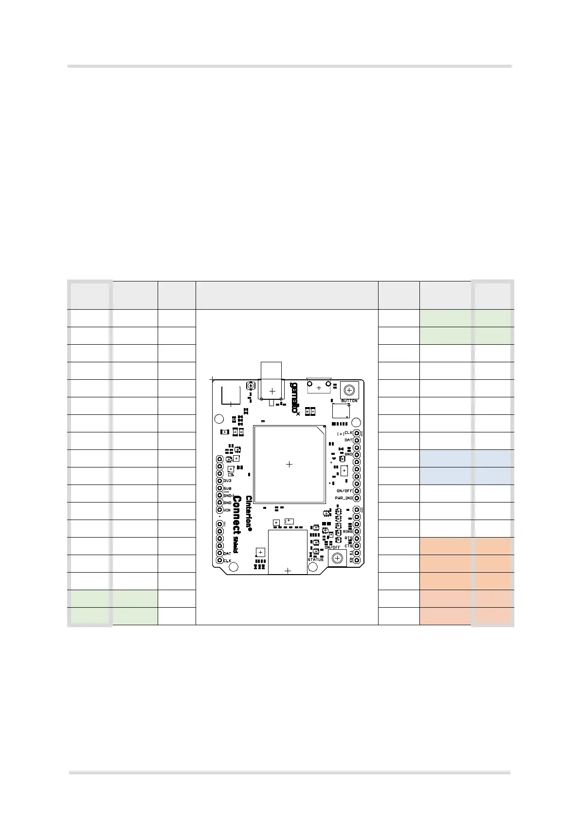
2.2.1 Pin Outline
A detailed pin description of the Arduino Uno interface is given following two tables.
Figure 2: Connect Shield’s Arduino UNO interface lines
Shield
I/F
Shield
function
Shield
DIR
Shield Interface (Concept Shield) Shield
DIR
Shield
function
Shield
I/F
I
SCL SCL
IO
SDA SDA
AREF
GND GND GND
NC - - - - SCK
IOREF - - - - MISO
RESET - - - - MOSI
3.3V PWR I - - CS
5V PWR I I
ON/OFF D9
GND PWR GND O
PWR_IND D8
GND PWR GND - - D7
Vin - - - - D6
A0 - - - - D5
A1 - - O
RING D4
A2 - - I
RTS D3
A3 - - O
CTS D2
SDA SDA IO I TXD TX
SCL SCL I O RXD RX