(5)
The following instructions are provided for those who
purchase a crossfader replacement unit from an authorized
Gemini dealer:
8. EQUALIZER: This unit features dual 7 band GRAPHIC EQUALIZERS
(8, 22) that allow you to adjust the sound to fit any room. Activate
the equalizer by pressing EQ BUTTON (28) (EQ LED is illuminated).
By adjusting any of the 7 LEFT equalizer slide controls (8), you can
cut or boost the tonal characteristics of the sound coming from the
LEFT speaker by ±12 dB. Adjusting any of the 7 RIGHT equalizer
slide controls (22) allows you to cut or boost the tonal
characteristics of the sound coming from the RIGHT speaker by ±12
dB. Deactivate the equalizer by pressing the EQ BUTTON (28) again
(EQ LED is OFF).
9. OUTPUT CONTROL: The level of the MAIN OUTPUT (34) is
controlled by the MASTER (24) slide. Activating the MONO (23)
button (MONO LED is illuminated) converts the overall output to
mono. The BOOTH (29) control adjusts the level of the BOOTH
OUTPUT (35).
HINT: BOOTH OUTPUT IS USED BY SOME DJS TO RUN
MONITOR SPEAKERS IN THE DJ BOOTH. IT IS ALSO USED AS
A SECOND ZONE OR AMP OUTPUT.
NOTE: REC OUTPUT HAS NO LEVEL CONTROL. LEVEL IS
CONTROLLED WITH THE CHANNEL SLIDES OF THE SELECTED
CHANNEL(S). TONE IS CONTROLLED VIA THE EQUALIZERS.
10.TALKOVER: The purpose of the talkover is to allow the program
playing to be muted so that the mic may be heard above the music.
The MIC/TALKOVER SWITCH (7) controls MIC 1 and MIC 2 and
has three settings.
• When MIC/TALKOVER (7) is in the BOTTOM position,
MIC 1, MIC 2 and TALKOVER are all OFF.
• When MIC/TALKOVER (7) is in the CENTER position, MIC 1
and MIC 2 are ON. MIC INDICATOR (6) glows/TALKOVER is OFF.
• When MIC/TALKOVER SWITCH (7) is in the TOP position,
MIC 1, MIC 2 and TALKOVER are ON and the volume of all
sources except MIC inputs is lowered by 16 dB.
11. TREBLE (2) and BASS (3) controls allow you to adjust the tone
of MIC 1 and MIC 2. MIC 1 LEVEL (5) controls the level of MIC 1
while MIC 2 LEVEL (4) controls the level of MIC 2.
12.CUE: By connecting a set of headphones to the HEADPHONE (32)
jack, you can monitor any or all channels. Press CUE ASSIGN (20)
buttons for Channels 1 through 4 and select the Channel(s) to be
monitored. The respective LED indicators will glow. Use the CUE
LEVEL (31) control to adjust the cue volume without changing the
overall mix. By moving the CUE PGM PAN (30) control to the LEFT
you will be able to monitor the assigned cue signal. Moving the
control to the RIGHT allows you to monitor PGM (program) output.
13.DISPLAY: The DISPLAY (21) indicates the MASTER output of the
left and right levels.
SPECIFICATIONS:
INPUTS:
Phono........................................................................................3 mV, 47 KOhm
Line........................................................................................150 mV, 27 KOhm
MIC 1 & MIC 2...............................................................1.5 mV, 2 K Ohm
Balanced
Bass....................................................................................................± 12dB
High......................................................................................................± 12dB
OUTPUTS:
Amp/Booth................................................................................0 dB 1V, 400
Ohm
Max........................................................................................20V Peak-to-Peak
Rec......................................................................................225 mV, 5 KOhm
GENERAL:
Frequency Response......................................................20Hz - 20KHz +/- 2 dB
Distortion...........................................................................................0.02%
S/N Ratio...............................................................................Better than 80 dB
Talkover Attenuation................................................................................-16 dB
Headphone Impedance...........................................................................16 Ohm
Echo......................................................................................600m sec
Power Source.....................................................115/230V, 50/60Hz, 10W
Dimensions..............................................19”w x 4”d x 9”h (483 x 94 x 221 mm)
Weight..................................................................................10.17 lbs. (4.6 Kg)
••
••
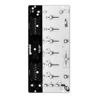
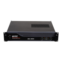
• Unscrew the FADER PLATE SCREWS (B).
••
••
• Do not touch the INSIDE SCREWS (C).
••
••
• Carefully lift the fader and unplug the CABLE (D).
••
••
• Plug the new fader into CABLE (D) and place it back in the mixer.
••
••
• Screw the fader to the mixer with the FADER PLATE SCREWS (B).
Description
Part #
Cabinet Parts and Packing
1
2
4
5
6
7
8
9
10
11
12
13
14
15
16
17
18
19
20
21
22
23
24
25
26
27
28
29
30
31
32
Item #
Parts Lists:
FACEPPMX1400
021-999
032-007
021-767
022-322
022-305
023-674
002-531
002-532
002-703
002-724
002-726
003-102
003-110
148-312
003-994
003-970
003-373
003-969
003-986
003-975
003-564
047-474
049-206
159-201
159-167
159-216
159-171
159-196
146-710
101-008
PANEL CONTROL
PANEL REAR
COVER BOTTOM
BRACKET VR
HOLDER X-FADER
PROTECTOR PLATE FOR 115/230V SWITCH
SWING LEVEL
KNOB PUSH (SMALL)
BUSHING FOR KNOB (SMALL)
KNOB SLIDE (SMALL)
KNOB SLIDE SILVER (BIG)
KNOB SLIDE SILVER (SMALL)
KNOB ROTARY (ASSIGN)
KNOB ROTARY (B)
KNOB INLAY (SILVER); LEVEL, BALANCE, CUE, ASSIGN
EQ VR INLAY
TRIM VR
INLAY PLATE
HOLDER LED 3f LED(17mm)
HOLDER LED
HOLDER LED
WASHER XLR
PCB SPACER SUPPORT
PAD FOOT
BNC DUST PROOF CLOTH
DUST PROOF CLOTH (VR)
DUST PROOF CLOTH (KNOB-SWING)
DUST PROOF CLOTH (VR)
FADER DUST PROOF CLOTH
GND SCREW
FLAT-HEAD MACHINE SCREW; FMS 2X4 (Y)
262-044
262-045
262-046
262-052
262-053
PRINTED CIRCUIT BOARD PDM24S-1:IN/OUT
PRINTED CIRCUIT BOARD PDM24S-2:MAIN
PRINTED CIRCUIT BOARD PDM24S-4:
FADER (73.5×13)
PRINTED CIRCUIT BOARD PDM14-3:PHONE
PRINTED CIRCUIT BOARD PDM14-5:
PHONE JACK (21×13)
Description Part #
Printed Circuit Boards
Item #
1
2
3
4
5
 Loading...