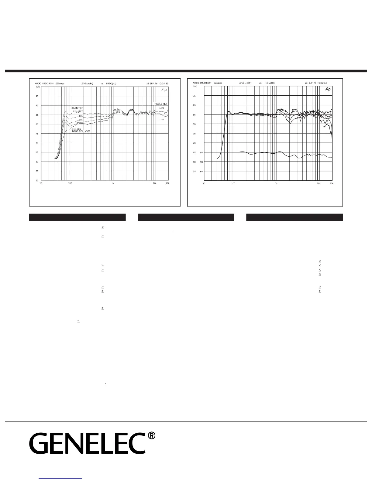
The curve above shows the effect of the ‘treble tilt’, ‘bass tilt’
and ‘bass roll-off ’ controls on the free field response.
The curve group shows the horizontal directivity characteristics
of the 1029A in its vertical configuration measured at 1m. The lower curve
shows the systems power response.
Bass amplifier output power with an 8 Ohm load:
Treble amplifier output power with an 8 Ohm load:
Long term output power is limited by driver unit
Amplifier system distortion at nominal output:
Signal to Noise ratio, referred to full output:
100/200, 115/230 or 230 V
Lower cut-off frequency, –3 dB:
Upper cut-off frequency, –3 dB:
Free field frequency response of system:
Maximum short term sine wave acoustic output on axis
in half space, averaged from 100 Hz to 3 kHz:
Maximum long term RMS acoustic output in same
conditions with IEC weighted noise (limited by driver unit
Maximum peak acoustic output per pair on top of
console, @ 1 m from the engineer with music material:
Self generated noise level in free field @ 1m on axis:
Harmonic distortion at 85 dB SPL @ 1m on axis:
Input 1: XLR female, balanced 10 kOhm
" Jack socket, balanced 10 kOhm
Input level for 100 dB SPL output at 1 m:
-6 dBu at volume control max
-65 dB relative to max output
Subsonic filter below 68 Hz :
1091A/7050A Subwoofer output (input 2) at 100db SPL:
Ultrasonic filter above 25 kHz:
Crossover frequency, Bass/Treble:
Crossover acoustical slopes:
Treble tilt control operating range:
Bass roll-off control operating in a –6 dB step @ 85 Hz
(to be used in conjunction with 1091A or 7050A
Bass tilt control operating range in –2 dB steps:
The ‘CAL’ position is with all tone controls set to ‘off’ and
the input sensitivity control to maximum (fully
AMPLIFIER SECTIONCROSSOVER SECTION
SYSTEM SPECIFICATIONS
FIN-74100, Iisalmi, Finland
Email genelec@genelec.com
In the U.S. please contact
Genelec, Inc., 7 Tech Circle
Email genelec.usa@genelec.com
001. Copyright Genelec Oy 6.2002. All data subject to change without prior notice
 Loading...