Genelec Oy, Olvitie 5Genelec Oy, Olvitie 5
Genelec Oy, Olvitie 5Genelec Oy, Olvitie 5
Genelec Oy, Olvitie 5
FIN - 74100 IISALMI, FINLANDFIN - 74100 IISALMI, FINLAND
FIN - 74100 IISALMI, FINLANDFIN - 74100 IISALMI, FINLAND
FIN - 74100 IISALMI, FINLAND
Phone:Phone:
Phone:Phone:
Phone:
+358 - 17 - 83 881+358 - 17 - 83 881
+358 - 17 - 83 881+358 - 17 - 83 881
+358 - 17 - 83 881
FF
FF
F
ax:ax:
ax:ax:
ax:
+358 - 17 - 812 267+358 - 17 - 812 267
+358 - 17 - 812 267+358 - 17 - 812 267
+358 - 17 - 812 267
E-mail:E-mail:
E-mail:E-mail:
E-mail:
genelec@genelec.comgenelec@genelec.com
genelec@genelec.comgenelec@genelec.com
genelec@genelec.com
Web:Web:
Web:Web:
Web:
http://www.genelec.comhttp://www.genelec.com
http://www.genelec.comhttp://www.genelec.com
http://www.genelec.com
Note! All frequency response curves were measured in aNote! All frequency response curves were measured in a
Note! All frequency response curves were measured in aNote! All frequency response curves were measured in a
Note! All frequency response curves were measured in a
calibrated, 12 m cube, anechoic chamber at 1 m using grade 1calibrated, 12 m cube, anechoic chamber at 1 m using grade 1
calibrated, 12 m cube, anechoic chamber at 1 m using grade 1calibrated, 12 m cube, anechoic chamber at 1 m using grade 1
calibrated, 12 m cube, anechoic chamber at 1 m using grade 1
measuring equipment. Input signal levels were set at -20 dBu.measuring equipment. Input signal levels were set at -20 dBu.
measuring equipment. Input signal levels were set at -20 dBu.measuring equipment. Input signal levels were set at -20 dBu.
measuring equipment. Input signal levels were set at -20 dBu.
The anechoic chamber error in the free field response is lessThe anechoic chamber error in the free field response is less
The anechoic chamber error in the free field response is lessThe anechoic chamber error in the free field response is less
The anechoic chamber error in the free field response is less
than 0.5 dB down to 60 Hz.than 0.5 dB down to 60 Hz.
than 0.5 dB down to 60 Hz.than 0.5 dB down to 60 Hz.
than 0.5 dB down to 60 Hz.
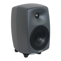
Figure 5. The curves above left show the effect of the 'bass tilt',
'bass level' and 'bass roll-off' controls on the free field response. The
curves to the right show the effect of the treble and midrange 'level'
controls.
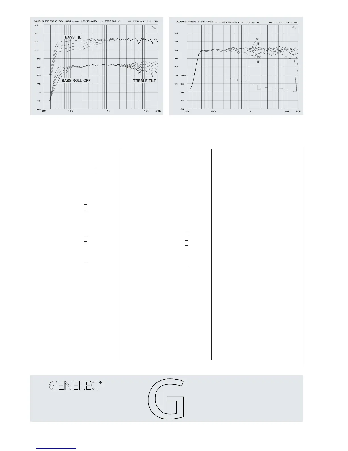
Figure 6. The upper curve group shows the horizontal directivity
characteristics of 1032A in its vertical configuration measured at 1m.
The lower curve is a 1/3 octave band power response, measured in
an IEC approved reverberation chamber.
SYSTEMSYSTEM
SYSTEMSYSTEM
SYSTEM
SPECIFICATIONSSPECIFICATIONS
SPECIFICATIONSSPECIFICATIONS
SPECIFICATIONS
AMPLIFIERAMPLIFIER
AMPLIFIERAMPLIFIER
AMPLIFIER
SECTIONSECTION
SECTIONSECTION
SECTION
CROSSOVERCROSSOVER
CROSSOVERCROSSOVER
CROSSOVER
SECTIONSECTION
SECTIONSECTION
SECTION
Genelec document DR32001
COPYRIGHT GENELEC OY 6/1999
All data subject to change without prior notice
Lower cut-off frequency, -3 dB: <40 Hz
Upper cut-off frequency, -3 dB: >22 kHz
Free field frequency response
of system: 42 Hz - 21 kHz (±2.5 dB)
Maximum short term sine wave acoustic
output on axis in half space, averaged from
100 Hz to 3 kHz: @1m >113 dB SPL
@0.5m >119 dB SPL
Maximum long term RMS acoustic output in
same conditions with IEC-weighted noise
(limited by driver unit protection circuit):
@1m >103 dB SPL
@0.5m >109 dB SPL
Maximum peak acoustic output per pair on
top of console, @ 1m from the engineer
with music material: >124 dB SPL
Self generated noise level in free field @ 1m
on axis: <10 dB
(A-weighted)
Harmonic distortion at 95 dB SPL at 1m on
axis:
50Hz...100 Hz <1%
freq. >100 Hz <0.5%
Drivers: Bass 10" (250 mm)
Treble 1" (25 mm) metal dome
Both drivers are magnetically shielded.
Weight: 21,7 kg (48 Ib.)
Dimensions: Height 495 mm (19
1
/
2
")
Width 320 mm (12
5
/
8
")
Depth 290 mm (11
7
/
16
")
Bass amplifier output power with a 4 Ohm
load: Short term 180 W
Treble amplifier output power with a 8
Ohm load: Short term 120 W
Long term output power is limited by
driver unit protection circuitry.
Slew rate : 80V/µs
Amplifier system distortion at
nominal output: THD <0.05%
SMPTE-IM <0.05%
CCIF-IM <0.05%
DIM 100 <0.05%
Signal to Noise ratio, referred to full output:
Bass >100 dB
Treble >100 dB
Mains voltage: 100/200V or 115/230V
Voltage operating range at 115V setting:
104 - 126V (±10%)
Power consumption:
Idle 50W
Full output 200W
Genelec Inc, 7 Tech CircleGenelec Inc, 7 Tech Circle
Genelec Inc, 7 Tech CircleGenelec Inc, 7 Tech Circle
Genelec Inc, 7 Tech Circle
Natick, MA 01760, USANatick, MA 01760, USA
Natick, MA 01760, USANatick, MA 01760, USA
Natick, MA 01760, USA
Phone:Phone:
Phone:Phone:
Phone:
+1+1
+1+1
+1
--
--
-
508/652-0900508/652-0900
508/652-0900508/652-0900
508/652-0900
Fax:Fax:
Fax:Fax:
Fax:
+1+1
+1+1
+1
--
--
-
508/652-0909508/652-0909
508/652-0909508/652-0909
508/652-0909
E-mail:E-mail:
E-mail:E-mail:
E-mail:
genelec.usa@genelec.comgenelec.usa@genelec.com
genelec.usa@genelec.comgenelec.usa@genelec.com
genelec.usa@genelec.com
Input connector: XLR female pin1 gnd
pin2 +
pin3 -
Input impedance: 10 kOhm
Input level for 100 dB SPL output @1m:
variable from +6 to -6 dBu
Input level for maximum short term output
of 113 dB SPL @1m:
variable from +19 to +7 dBu
Subsonic filter below 40 Hz :
18 dB/octave
Ultrasonic filter above 25 kHz:
12 dB/octave
Crossover frequency: 1.8 kHz
Crossover acoustical slopes:
24 - 32 dB/octave
Treble tilt control operating range in 2dB
steps: from+2 to -4dB & MUTE
Bass roll-off control in 2 dB steps:
from 0 to -8 dB @40 Hz
Bass tilt control in 2 dB steps:
from 0 to -8 dB @80 Hz
The 'CAL' position is with all tone controls
set to 'off' and input sensitivity control to
maximum.
 Loading...