32 Owner’s Manual for Mobile Generator
Operation
Note: When using transfer switch in AUTO mode, the
Engine Speed switch must be in the RUN position.
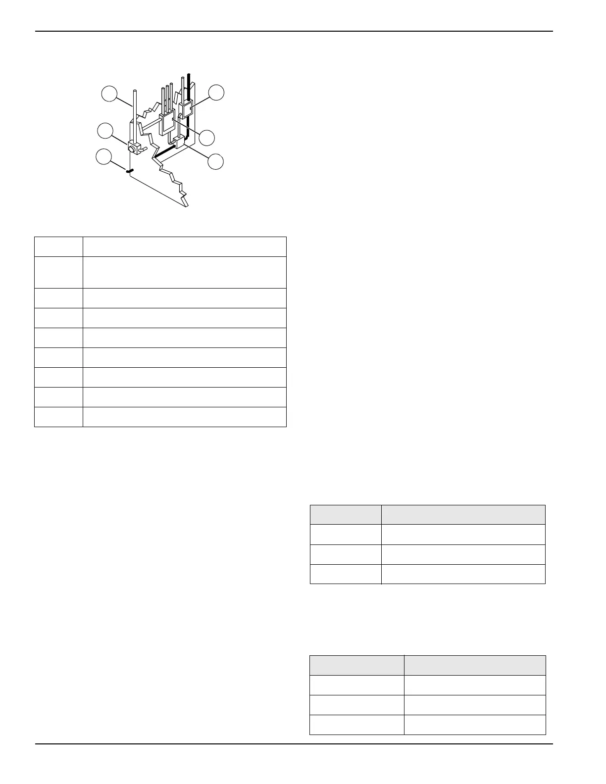
Figure 3-6. Transfer Switch Operation
Alternative Load Device (ALD) (If
Equipped)
The ALD system mitigates wet-stack and low-load
conditions by increasing engine load. It monitors
generator load, activating when power capacity is under-
utilized, and deactivating when generator is appropriately
loaded—or as needed, to maintain appropriate engine
temperature.
The ALD device is a fluid (coolant) shearing device,
routing some coolant from the engine to the cylinder
head. The device is belt driven, powered by the
crankshaft pulley.
See Maintenance for maintenance requirements.
AUTO Exercise Timer
The controller is capable of starting and stopping the unit
automatically, based on a programmable schedule.
Units installed in a standby application should be
exercised regularly to maintain operating condition and to
ensure responsiveness in an emergency situation.
Proceed as follows to operate the unit in AUTO mode:
Accessing the Configuration Menu
1. With the unit stopped, press ▲, ►, ▼, or ◄ to
navigate to the maintenance screens from any of
the operator screens.
2. While on any maintenance screen, press and O
simultaneously. The controller will display the
Configuration menu.
3. To save any changes and exit the Configuration
menu, press and hold for five seconds. To
cancel any changes and return to the maintenance
screen, press and hold O for five seconds.
Set the Controller Clock
The schedule runs based on the time set in the controller
clock. Proceed as follows to set the controller clock
before setting the schedule:
1. Navigate to the maintenance group and press ► to
access it.
2. Press ► to select the time section.
3. Set the time and date to the correct local time.
Set the Schedule
NOTE: The controller must be in AUTO mode to run at
the programmed time. Use a trickle or solar battery
charger to prevent the controller from draining the battery
while in AUTO mode.
1. Access the scheduler group by pressing the ►
button.
NOTE: The scheduler group consists of the scheduler
options and scheduler setup sections. Each section can
be accessed and exited using the ► and ◄ buttons.
2. Access the scheduler options section. Within this
section, the scheduler can be enabled, run mode
selected, and load mode selected.
3. Access the scheduler setup section. In this section,
each schedule entry can be modified by pressing
the button to select the item, and the ▲ and ▼
buttons to define them.
A Incoming utility power
B
Emergency distribution panel (generator
power)
C Main distribution panel (utility power)
D Transfer switch
E Power from generator
F Utility meter
WHITE Incoming utility power
GRAY Normal utility power circuit
BLACK Emergency generator power circuit
Item Values
Enable Yes, No
Run Mode Monthly, Weekly
Load Idle, In Island, On Load, Off Load
Item Values
Schedule Entry 1-16
Start Time 00:00-23:59
Duration 00:00-99:59