Do you have a question about the Generac Power Systems 0043736, 0046265 and is the answer not in the manual?
Details on the operator's responsibility for safe operation and routine maintenance.
Instructions on contacting a Generac/Guardian Authorized Dealer for service.
Crucial safety guidelines for installation, operation, and maintenance.
General safety precautions and hazards associated with the generator.
Warnings and precautions related to electrical shock and hazards.
Safety advice concerning fire risks and prevention measures.
Precautions to avoid explosion risks from fuel and gases.
Procedure for unpacking and inspecting the generator for damage.
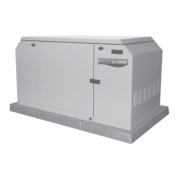
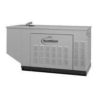
Overview of the liquid-cooled Guardian generator's purpose and use.
Explanation of the single-phase generator AC connection system.
Information about the NEMA 3R enclosure transfer switch.
Description of how the generator operates automatically during utility failure.
Details on the generator's main circuit breaker.
Explanation of safety switches that shut down the engine.
Technical specifications for the generator models.
Ensuring compatibility between the generator and electrical loads.
Detailed engine specifications and features.
Guidelines for using natural gas and LP gas fuels.
Recommended engine oil types and viscosity based on temperature.
Information on recommended coolant mixture and safety precautions.
Details on the emission control system for specific models.
General safety and requirements for standby generator installation.
List of relevant National Fire Protection Association standards.
References to other applicable building and agricultural standards.
Schematic and function of a basic standby electric system.
Method to prevent generator overloading by isolating critical loads.
Method for generators powering all electrical loads.
Requirements for proper grounding of the generator frame.
Information on generator AC neutral connections.
Wiring connections for transfer switch start signals.
Safety precautions and procedures for installing the battery.
Specific procedures and cautions for handling vented batteries.
Steps to prepare the generator before initial start-up.
Description of the components on the generator control console.
Instructions for operating the AUTO/OFF/MANUAL switch.
Procedure to set up and initiate automatic transfer operation.
Detailed steps of the automatic generator operation sequence.
Information on the generator's engine block heater.
How to program and manage the weekly generator exercise cycle.
Procedure for checking and maintaining the engine oil level.
Steps for performing engine oil and filter changes.
Procedure for replacing the engine air cleaner element.
Maintenance and adjustment of spark plugs.
Inspection and maintenance procedures for the generator battery.
Ensuring proper cooling system operation and airflow.
Details on DC electrical system overload protection.
Information on the 15-amp DC fuse for the control circuit.
Checking and maintaining the engine coolant level.
General maintenance tasks like cleaning and rodent protection.
Steps for preparing the generator for long-term storage.
Recommended service intervals for various generator components.
Guide to identify and correct common generator problems.
Diagram showing installation layout and dimensions.
Electrical schematic for the stepper motor control.
Wiring diagram for the pre-pack control panel.
Wiring diagram for the lower control panel.
Wiring diagram for the control panel.
Electrical schematic for the control panel.
Wiring diagram for engine components.
Wiring diagram for engine components.
Exploded view and parts list for the generator mounting base.
Exploded view and parts list for the generator compartment.
Exploded view and parts list for the 4.3L control panel.
Exploded view and parts list for the control panel.
Exploded view and parts list for the connection box.
Exploded view and parts list for the generator assembly.
Exploded view and parts list for the engine assembly.
Exploded view and parts list for the engine assembly.
Exploded view and parts list for the 4.3L radiator.
Exploded view and parts list for the 4.3L exhaust system.
Exploded view and parts list for the 4.3L natural gas fuel system.
Exploded view and parts list for the 4.3L natural gas fuel system.
Exploded view and parts list for the exhaust system.
Statement of warranty rights and obligations for California emissions.
Details on the ECS warranty coverage and covered parts.
Two-year limited warranty for Guardian standby generators.
| Brand | Generac Power Systems |
|---|---|
| Model | 0043736, 0046265 |
| Category | Inverter |
| Language | English |