Generac
®
Power Systems, Inc. 23
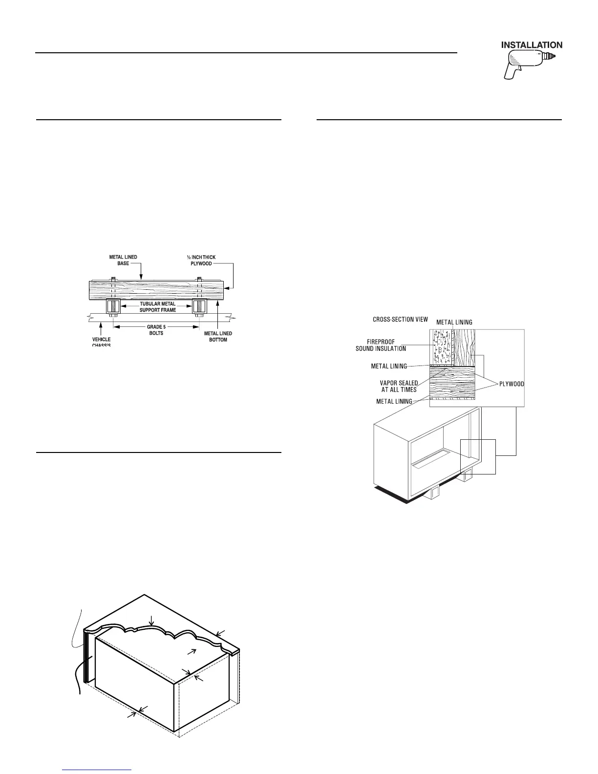
2.1.4 GENERATOR RESTRAINT
Use four 3/8"-16 hardened steel bolts (Grade 5) to fas-
ten the generator to the supporting frame or the sup-
port tubing. These bolts must pass through (a) the gen-
erator mounting base, (b) the compartment floor (if a
compartment is used) and (c) the supporting frame-
work (Figure 2.3). All bolts must be long enough so that
when tight, at least three threads are visible past the
retaining lock nuts. Refer to Section 2.2 for the location
of the generator mounting holes.
Figure 2.3 – Typical Generator Restraint
2.2 GENERATOR COMPARTMENTS
Whether the generator set is being installed inside a
compartment specifically manufactured to house a gen-
erator or inside a compartment that the installer con-
structs, the compartment MUST meet certain specifi-
cations as outlined in the following sections:
2.2.1 COMPARTMENT SIZE
Plan the compartment size carefully. Provide a mini-
mum clearance of 1/2 inch (13 mm) on the front and
top, 1/2 inch (25 mm) on the sides, and 1/2 inch (13
mm) from the back for air circulation AFTER the
compartment has been lined with metal and sound
insulation (Figure 2.4).
NOTE:
Refer to “Figure 1.2 – Major Features and
Dimensions” on Page 21.
Figure 2.4 – Clearances
2.2.2 COMPARTMENT CONSTRUCTION
• The generator compartment should be either con-
structed of, or lined with, 26-gauge galvanized
steel.
NOTE:
Aluminum is NOT an acceptable alternative
to galvanized steel due to aluminum’s low
melting point.
• If the compartment is lined with galvanized steel, it
may be constructed of any material. Generac rec-
ommends that the compartment be constructed of
1/2-inch thick plywood (not strandboard), with the
floor made of a double thickness of 1/2-inch ply-
wood with the grain of the wood at cross section
for added strength (Figure 2.5).
Figure 2.5 – Typical Compartment Construction
• If constructing a compartment, line the exterior
(underside) of the compartment floor with 26-
gauge galvanized steel.
• All seams, splices and joints of the compartment
walls (unless vapor tight by design) should
be caulked to prevent poisonous, flammable or
explosive vapors from entering the vehicle interior.
NOTE:
Caulking must be done so that the caulking materi-
al will stay in place permanently. Pressing such
materials as putty tape onto joints and seams is NOT
acceptable. A high quality silicone rubber base
sealant is recommended.
• Holes and openings made in the compartment
walls to allow for the passage of electrical conduit,
conductors, hoses, cables, etc., into the vehicle liv-
ing area must be sealed vapor tight with silicone
rubber base sealant.
◆

 Loading...