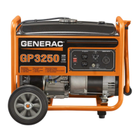
1.1 UNPACKING
• Remove all packaging material.
• Remove separate accessory box.
• Remove the generator from carton.
1.1.1 ACCESSORY BOX
Check all contents. If any parts are missing or damaged locate an
authorized dealer at 1-888-436-3722.
Contents Include:
• 1 – Owner’s Manual • 1 - Left Handle Assembly
• 1 - Quart Oil SAE 30 • 1 - Right Handle Assembly
• 2 - Never-Flat Wheels • 1 - Frame Foot
• 1 - Foot Support
• 1 - Hardware Bag (containing the following):
2 - Rubber Feet 2 - 5/16” Bolts
2 - 5/16” Flat Washers 4 - 5/16” Locking Flange
Nuts
4 - 5/16” Carriage Bolts 2 - 5/16” Locking Cap Nuts
2 - 1/2” Axle Bolts 2 - 1/2” Locking Flange Nuts
2 - 1/2" Flat Washers
1.2 ASSEMBLY
The generator requires some assembly prior to using it. If
problems arise when assembling the generator, please call the
Generator Helpline at 1-888-436-3722.
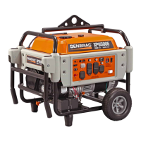
1.2.1 ASSEMBLING THE ACCESSORY KIT
The wheels are designed into the unit to greatly improve the
portability of the generator.
NOTE:
The wheels are not intended for over-the-road use.
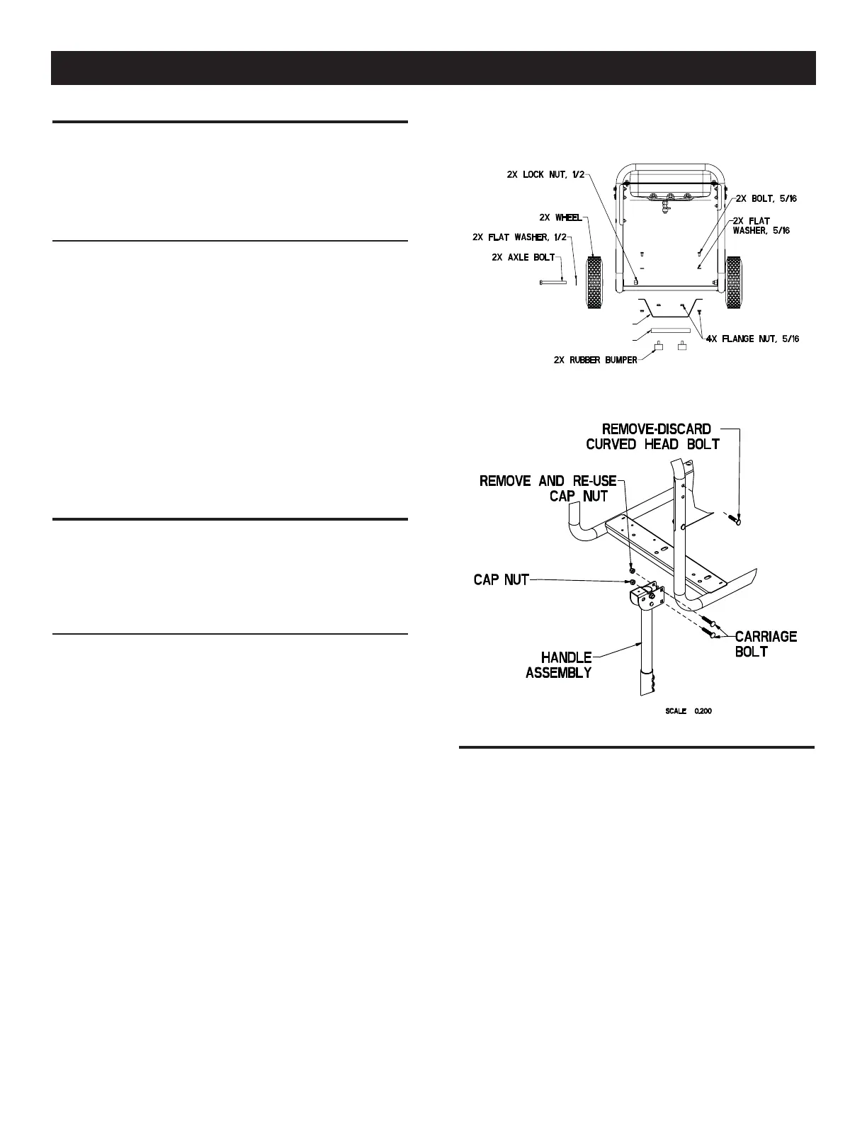
1. Refer to Figure 1 and install Wheels as follows:
• Slide the 1/2” Axle Bolt through the Wheel and Wheel bracket
on frame.
• Install 1/2” Locking Flange Nuts onto 1/2” Flange Bolt.
2. Refer to Figure 1 and install Frame Foot and Rubber Feet as
shown.
• Slide Rubber Foot stud through Frame Foot; Install 5/16”
Locking Flange Nuts Slide 5/16” Bolt through 5/16” Flat
Washer and then through holes in Frame Rail.
• Slide Frame Foot onto 5/16” Bolts; Install 5/16” Locking
Flange Nuts.
3. Refer to Figure 2 and install Handles as shown.
• Remove top Curved Head Bolts and Cap Nuts (Cap Nuts will
be re-used).
• Slide Handle Assembly over Frame Tube, aligning 2 holes.
• Slide 5/16” Carriage Bolts through; Install 5/16” Cap Nuts.
Figure 1 – Wheel Assembly
FOOT SUPPORT
FOOT
Figure 2 – Install Handle Kit
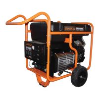
2.1 KNOW THE GENERATOR
Read the Owner’s Manual and Safety Rules before operating
this generator.
Compare the generator to Figures 3 through 5 to become
familiarized with the locations of various controls and adjustments.
Save this manual for future reference.
1. 120 Volt AC, 20 Amp, Duplex Receptacle – Supplies electrical
power for the operation of 120 Volt AC, 20 Amp, single-phase,
60 Hz electrical lighting, appliance, tool and motor loads.
2. 120/240 Volt AC, 30 Amp Locking Receptacle – Supplies
electrical power for the operation of 120 and/or 240 Volt AC,
30 Amp, single-phase, 60 Hz, electrical lighting, appliance,
tool and motor loads.
3. Circuit Breakers (AC) – Each receptacle is provided with a
push-to-reset circuit breaker to protect the generator against
electrical overload.
4
General Information
 Loading...