Section 2: General Information and Setup
4 Owner’s/Installation Manual for SMM
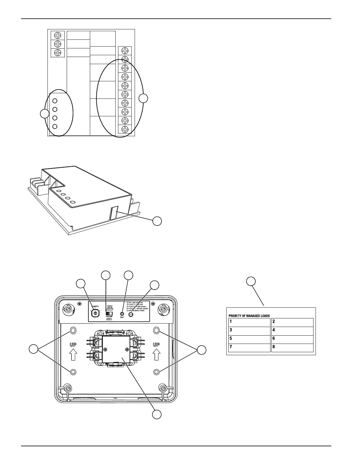
Figure 2-1. Smart A/C Module
Figure 2-2. Smart A/C Module Test Button
Know Your Smart Management
Module and Carton Contents
Priority Dial (A) – Sets module priority.
NOTE: PRIORITY MUST BE DIFFERENT for each
module in an installation. Priority sets the order in
which loads recover from a load shed event. Recovery
time from a load shed event is five minutes for Priority 1.
Each priority after Priority 1 waits an additional 15
seconds after the initial recovery time. See Table 2-1.
Lockout Switch (B) – Prevents load from operating
when system is operating under generator power. See
Table 2-2.
NOTE: Recovery time is based on priority dial settings.
See Table 2-1.
Test Button (C) – Disables contactor output for a
specified time.
LED (D) – Provides module status. See Table 2-3.
Contactor (E) – Controlled by a smart controller in
module. Contactor remains CLOSED until generator
power is required. Upon generator activation, controller
moves to OPEN to handle overload conditions.
NOTE: The contactor is also opened during lockout
switch ACTIVE state.
Mounting Holes (F) – Internal enclosure mounting holes
provide clean and sturdy mounting.
Priority Decal (G) – Provided for recording priority of
each module in installation. Should be installed on
electrical panel.
Figure 2-3. SMM Features and Controls
0 GROUND
194 +12V
23 TRANSFER
A/C 1
A/C 2
A/C 3
A/C 4
A/C 1
A/C 2
A/C 3
A/C 4
T1
NEUTRAL
000802
000143a