Do you have a question about the Generac Power Systems 04389-2, 04456-2, 04390-2 and is the answer not in the manual?
Emphasizes manual reading, explains safety symbols, and operator responsibilities.
Lists manual topics and provides instructions for obtaining service and locating dealers.
General safety guidelines for installation, operation, and maintenance.
Details hazards like exhaust, electrical, mechanical, and California specific warnings.
Covers specific risks related to electricity, fire, and fuel explosions.
Lists relevant codes and standards for equipment installation.
Instructions for checking the generator and describes engine protection features.
Explains the requirement for AFCI breakers in bedrooms according to the National Electric Code.
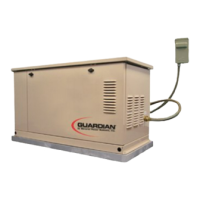
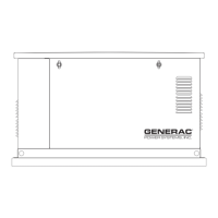
Identifies key components of the generator unit for both models.
Details electrical, physical, and engine specifications for all models.
Explains LED indicators, fuel types, quality, and pressure needs.
Provides fuel consumption data and instructions for fuel system reconfiguration.
Details fuel system changes and requirements for generator placement.
Specifies indoor installation requirements for the transfer switch enclosure.
Instructions for battery installation, type, and handling precautions.
Pre-start checks, transfer switch operation, and verifying electrical connections.
Refers to manual operation procedures for the transfer switch.
Steps to test the generator's performance with electrical loads applied.
Procedure to verify the generator's automatic start and transfer sequence.
Guide for adjusting the fuel regulator for optimal performance on natural gas.
Instructions for adjusting governor for frequency and regulator for voltage.
Recommendations for spraying engine linkage parts with corrosion inhibitor.
Recommended steps for breaking in the generator for optimal future operation.
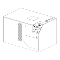
Explains the function and operation of the AUTO/OFF/MANUAL control switch.
Outlines the steps to set up the system for automatic operation during power outages.
Describes the step-by-step process of the generator starting and transferring loads.
Detailed instructions for manually starting the generator and transferring loads.
Guide on setting the exercise timer and explains protection system functions.
Identifies fuses and provides instructions for checking engine oil level.
Procedures for changing engine oil and replacing the oil filter.
Procedure for inspecting and replacing the engine air cleaner element.
Guidance on spark plug service and battery inspection/maintenance.
Instructions for adjusting valve clearance and maintaining the cooling system.
Procedures for handling submersion, corrosion prevention, and preparing for storage.
A comprehensive schedule outlining inspection, cleaning, and replacement intervals.
A table listing common problems, their causes, and suggested corrections.
Defines symbols and abbreviations used in the electrical diagrams.
Electrical wiring diagram for 12 kW and 15 kW models.
Detailed electrical schematic for 12 kW and 15 kW models.
Continuation of the electrical schematic for 12 kW and 15 kW models.
Electrical wiring diagram for the 7 kW model.
Continuation of the electrical schematic for the 7 kW model.
Electrical schematic for the 7 kW model.
Continuation of the electrical schematic for the 7 kW model.
Exploded view and parts list for the generator enclosure.
Continuation of the enclosure exploded view and parts list.
Exploded view and parts list for the control panel assembly.
Continuation of the control panel exploded view and parts list.
Exploded view and parts list for the 7 kW load center assembly.
Continuation of the 7 kW load center exploded view and parts list.
Exploded view and parts list for 12/15 kW load center assembly.
Continuation of the 12/15 kW load center exploded view and parts list.
Exploded view and parts list for the GT-990 engine (Part 1).
Continuation of the GT-990 engine exploded view and parts list.
Exploded view and parts list for the GT-990 engine (Part 2).
Continuation of the GT-990 engine exploded view and parts list.
Exploded view and parts list for the 7 kW generator.
Continuation of the 7 kW generator exploded view and parts list.
Exploded view and parts list for 12/15 kW generator.
Continuation of the 12/15 kW generator exploded view and parts list.
Exploded view and parts list for GN410 engine (Part 1).
Continuation of the GN410 engine exploded view and parts list.
Exploded view and parts list for GN410 engine (Part 2).
Continuation of the GN410 engine exploded view and parts list.
Details warranty rights and obligations specific to California emissions standards.
Outlines the owner's responsibilities regarding warranty claims and maintenance.
Specifies the warranty period and coverage for emission control components.
Lists owner's duties to maintain warranty validity, including required maintenance.
Explains the scope and applicability of the ECS warranty for engine emissions components.
Outlines warranty coverage periods and lists conditions where warranty does not apply.
| Brand | Generac Power Systems |
|---|---|
| Model | 04389-2, 04456-2, 04390-2 |
| Category | Inverter |
| Language | English |