ALTERNATOR AC LEAD
CONNECTIONS
The electrical wires in the unit’s AC connection (lower) panel
should be installed according to the number of leads and the
voltage/phase required for the application. The voltage and phase
are described on the generator data label. The number of lead
wires can be identified using the Specifications section and the
power output rating on the generator data label. For example, if
the generator produces 130kW, 277/480 Volt, 3-phase power, the
generator has 12 alternator output leads. Figure 7.3 describes the
stator power winding connection for the generator.
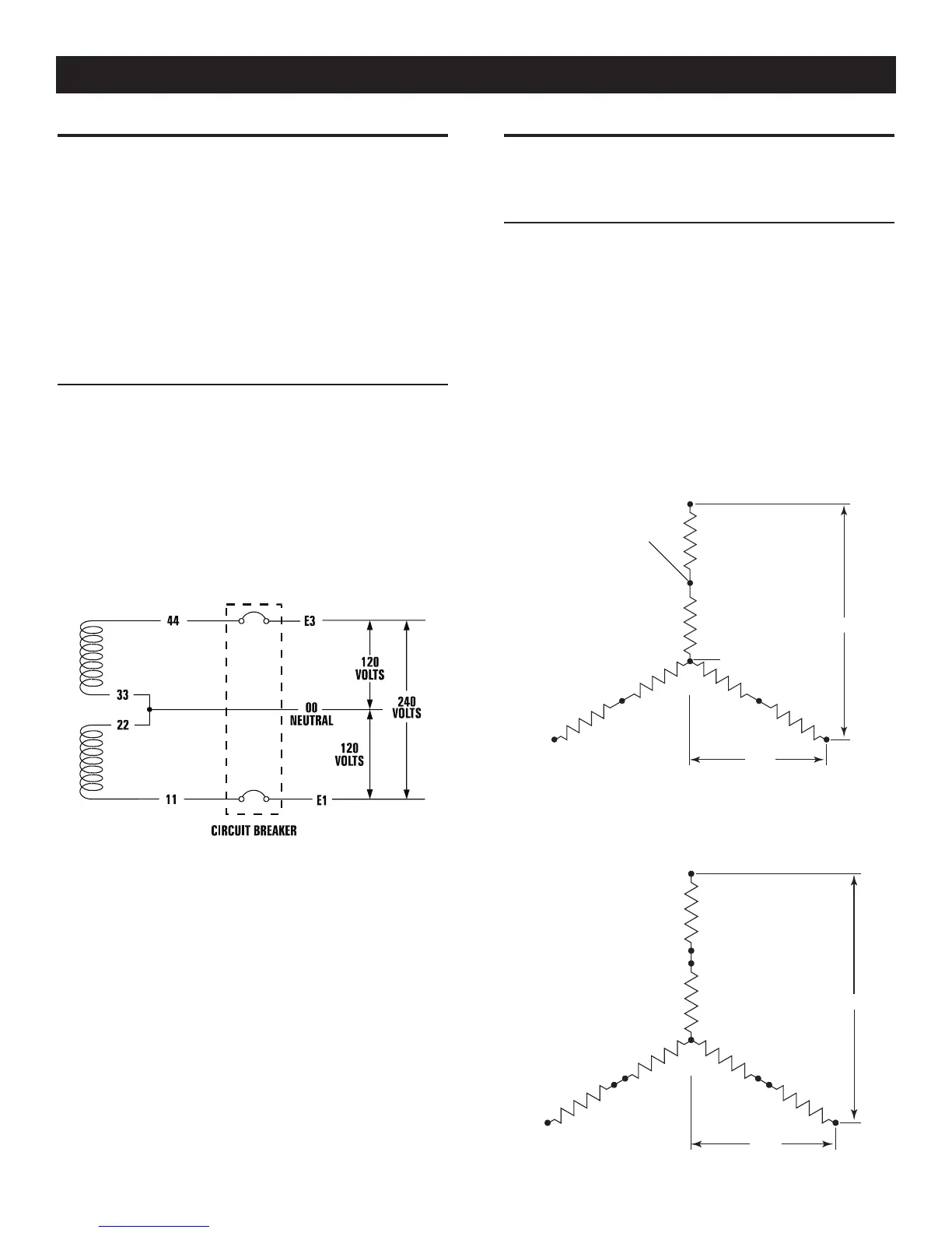
FOUR-LEAD, SINGLE-PHASE STATOR
Four-lead alternators (see Figure 7.1) are designed to supply elec-
trical loads with voltage code “A” (240V, 1-phase, 60 Hz). Electrical
power is produced in the stator power windings. These windings
were connected at the factory to the main circuit breaker as shown
in Figure 7.1.
The rated voltage between each circuit breaker terminal is 240V.
The rated voltage between each circuit breaker terminal and the
neutral point 00 is 120V.
Figure 7.1 — Four-lead, Single-phase Stator
ALTERNATOR POWER WINDING
CONNECTIONS
3-PHASE ALTERNATORS ("Y" CONFIGURATION)
The Stationary Emergency Generator is designed to supply
3-phase electrical loads. Electric power is produced in the alterna-
tor power windings. These windings were connected at the factory
to the main circuit breaker with a “Y” configuration as shown in
Figures 7.2 through 7.6.
The rated voltage between circuit breaker terminals E1-E2, E1-E3
and E2-E3 is 480V, 208V or 600V depending on the model.
The rated voltage between each circuit breaker terminal and the
neutral point 00 is 277V, 120V, or 346V depending on the model.
Figure 7.2 — Stator Power Winding
Connections - 3-phase, 277/480V (6 Lead)
E1
S1
S6
S5
S4
S2
E2
S3
E3
L - N
L - L
INTERNAL
CONNECTIONS
00 (NEUTRAL)
Figure 7.3 — Stator Power Winding
Connections - 3-phase, 277/480V (12 Lead)
E1
S1
S4
S7
S12
S11
S10
S8
S5
S2
E2
S9
S6
S3
E3
L - N
L - L
7-1
ACConn007 Rev. B 05/10
General Information