
D
Dana WilliamsJul 28, 2025
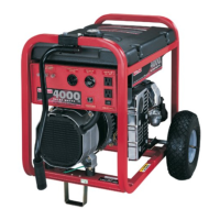
What to do if no-load voltage and frequency falls off under load on Generac Power Systems 4451 & 4986?
- EerinoconnellJul 28, 2025
If the no-load voltage and frequency falls off under load on your Generac Power Systems Portable Generator, proceed to the voltage regulator adjustment.