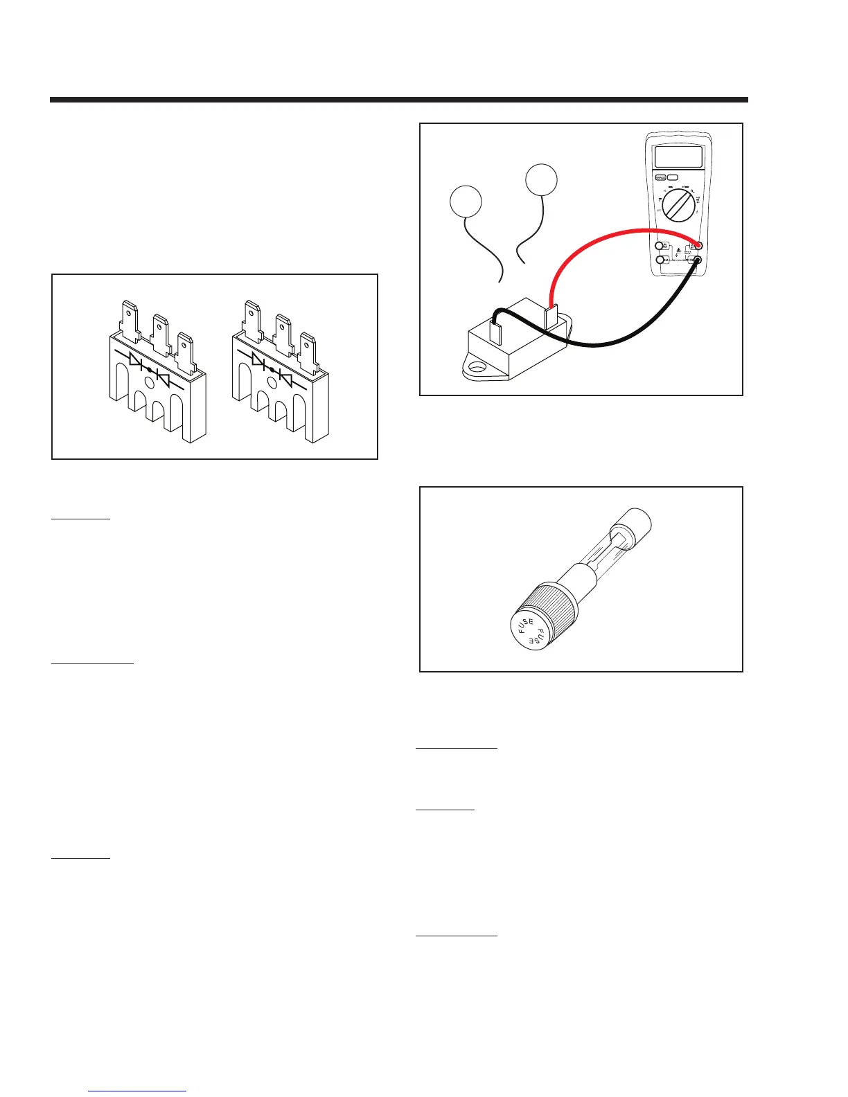
Short to Ground:
4. Set the VOM to measure resistance. Connect the positive (+)
test lead to the case housing of the BCR. Connect the negative
(-) test lead to an outer terminal. INFINITY should be mea
-
sured. Now connect the negative test lead to the BCR center
terminal. INFINITY should be measured. Next, connect the
negative test lead to the remaining outer BCR terminal. Once
again INFINITY should be measured.
Figure 6-25. – Battery Charge Rectifier
RESULTS:
1. If any of the previous steps has failed, replace the Battery
Charge Rectifier.
2. If the BCR tests good, refer back to the flow chart.
TEST 20 - CHECK 10 AMP CIRCUIT BREAKER
PROCEDURE:
1. Set a voltmeter to measure resistance.
2. Locate the 10 Amp circuit breaker (CB1) in the control panel.
See Page 17 for Circuit breaker location.
3. Disconnect Wire 15A and Wire 13A from the circuit breaker.
4. Connect one meter test lead to one terminal of the circuit
breaker. Connect the other meter test lead to the remaining
terminal on the circuit breaker. Continuity should be measured.
See Figure 6-26.
RESULTS:
1. If continuity was measured the breaker is good refer back to the
flow chart.
2. If INFINITY or a open condition was measured replace the
circuit breaker.
10A CIRCUIT BREAKER (CB1)
13A
00.00
15A
Figure 6-26. – Testing 10 Amp Breaker
TEST 21- CHECK 10 AMP FUSE
Figure 6-27. – 10 Amp Fuse (Located in Rear of
Control Panel)
PROCEDURE:
Push in on fuse holder cap and turn counterclockwise.
Then, remove the cap with fuse. Inspect the Fuse.
RESULTS:
If the Fuse element has melted open, replace the
Fuse with an identical size fuse. If Fuse is good, refer
back to flow chart.
TEST 22- CHECK BATTERY & CABLES
PROCEDURE:
1. Inspect the battery cables and battery posts or terminals for
corrosion or tightness. Measure the voltage at the terminal of
the Starter Contactor and verify 11-12 volts DC is available to
the generator during cranking. If voltage is below 11 volts DC,
Section 6
DIAGNOSTIC TESTS
Page 48
 Loading...