15
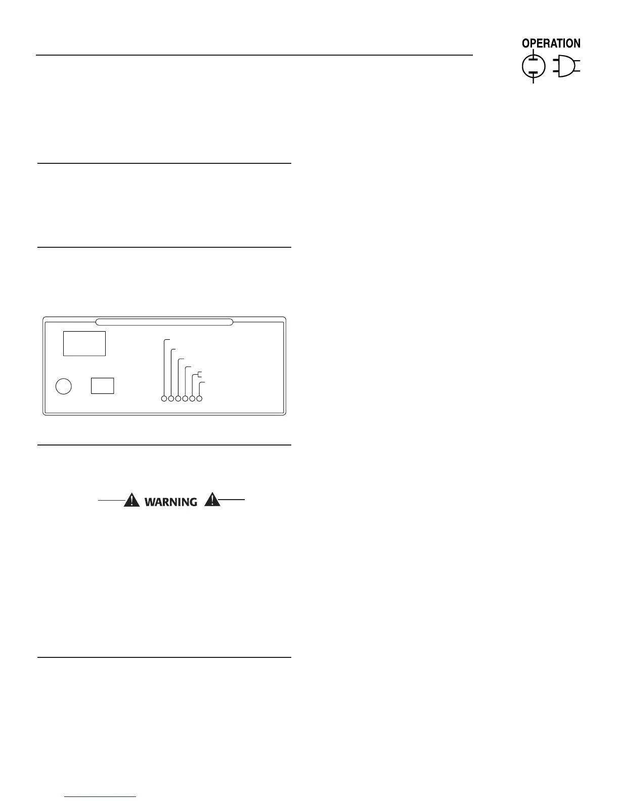
3.1 USING THE AUTO/OFF/MANUAL
SWITCH (FIGURE 3.1)
3.1.1 “AUTO” POSITION
Selecting this switch position activates fully automatic
system operation. It also allows the unit to automati-
cally start and exercise the engine every seven days
with the setting of the exercise timer (see the Setting
the Exercise Timer section).
3.1.2 “OFF” POSITION
This switch position shuts down the engine. This
position also prevents automatic operation.
Figure 3.1 – Generator Control Panel
OFF
EXERCISE
SYSTEM FUSE
15A
ASSY: 0F8418/0F8419
SET
TIME
AUTO. MAN.
NO UTILITY SENSE
5 FLASHING RED LEDS=
EXERCISER NOT SET
FLASHING GREEN LED=
SYSTEM SET
NO RPM SENSE IF FLASHING
OVER SPEED
CONTROL AND INFORMATION CENTER
LOW BATTERY
LOW OIL
HIGH TEMP
OVER CRANK
3.1.3 “MANUAL” POSITION
Set the switch to MANUAL to crank and start the
engine. Transfer to standby power will not occur
unless there is a utility failure.
With the switch set to AUTO, the engine may
crank and start at any time without warning.
Such automatic starting normally occurs when
utility power source voltage drops below a pre-
set level or during the normal exercise cycle. To
prevent possible injury that might be caused
by such sudden starts, always set the switch to
OFF and remove the fuses before working on or
around the generator or transfer switch. Then,
place a “DO NOT OPERATE” tag on the genera-
tor panel and on the transfer switch.
3.1.4 CHOKE OPERATION
1. 990 engines have an electric choke in the air box
that is automatically controlled by the electronic
control board.
2. 530 engines have an electric choke on the divider
panel air inlet hose that is automatically con-
trolled by the electronic control board.
3. 410 engines have a choke behind the air box that
is automatically controlled by the electronic con-
trol board.
3.2 AUTOMATIC TRANSFER
OPERATION
To select automatic operation, do the following:
1. Make sure the transfer switch main contacts are
set to their UTILITY position, i.e., loads con-
nected to the utility power source (Figure 3.2).
2. Be sure that normal UTILITY power source volt-
age is available to transfer switch terminal lugs
N1 and N2 (Refer to the Electrical Data section).
3. Set the generator’s AUTO/OFF/MANUAL switch to
AUTO.
4. Set the generator’s main circuit breaker to its ON
(or CLOSED) position.
With the preceding steps complete, the generator will
start automatically when utility source voltage drops
below a preset level. After the unit starts, loads are
transferred to the standby power source. Refer to the
Sequence of Automatic Operation section.
3.3 SEQUENCE OF AUTOMATIC
OPERATION
The generator’s control panel houses a control logic
circuit board. This board constantly monitors util-
ity power source voltage. Should that voltage drop
below a preset level, circuit board action will signal
the engine to crank and start. After the engine starts,
the circuit board signals the transfer switch to acti-
vate and connect load circuits to the standby power
supply (load terminal lugs T1/T2 connect to terminal
lugs E1/E2). Refer to the Electrical Data section.
The generator must run at 50 Hz or greater for the
transfer output to be activated. Once activated, it will
remain active even if the frequency dips below 50
Hz.
Upon restoration of utility source voltage above a
preset level, generator circuit board action signals the
transfer switch to transfer loads back to that power
supply. After retransfer, the engine is signalled to shut
down.
The actual sequence of operation is controlled by
sensors and timers on a control logic circuit board,
as follows:
A. Utility Voltage Dropout Sensor
• This sensor monitors utility source voltage.
• If utility source voltage drops below about 65
percent of the nominal supply voltage, the sensor
energizes a 10 second timer.
• Once the timer has expired, the engine will crank
and start if utility is still low.
B. Engine Warm-up Time Delay
• This mechanism lets the engine warm up for
about five (5) seconds before the load is trans-
ferred to the standby source.
Section 3 — Operation
Air-cooled Generators