Section 1 — General Information
Air-cooled Generators
5
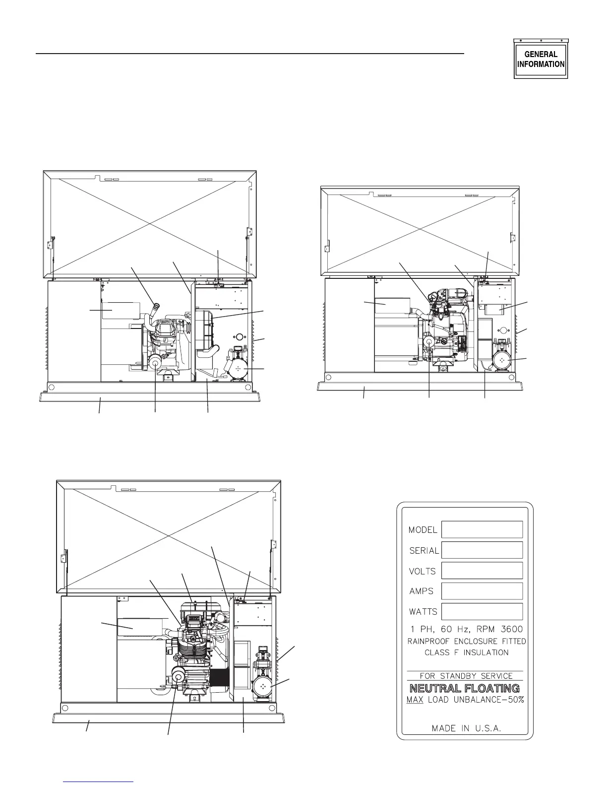
1.4 THE GENERATOR
Oil
Dipstick
Data Label
(see sample)
Air Filter
Cover
Control
Panel
Fuel
Inlet
(back)
Fuel
Regulator
Battery CompartmentOil FilterComposite Base
Exhaust
Enclosure
Air Filter
Cover
Control
Panel
Fuel
Regulator
Battery Compartment
Oil Filter
Exhaust
Enclosure
Oil
Dipstick
Composite Base
Fuel
Inlet
(Back)
Data Label
(see sample)
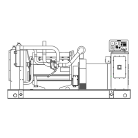
Figure 1.3 – 13, 16 and 18kW, V-twin, GT-990 Engine
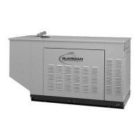
Figure 1.1 – 7kW, Single Cylinder, GH-410 Engine
Cerramiento
para los gases
de escape
Varilla medidora
de aceite
Etiqueta de datos
(consulte la muestra)
Panel de
contrrol
Filtro de aire
Entrada de
combustible
(parte trasera)
Regulador
de combustible
Compartimiento de la bateríaFiltro de aceiteBase compuesta
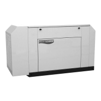
Figure 1.2 – 10kW, V-twin, GT-530 Engine
Data Label Sample