Installation, Tests, & Troubleshooting
10 Owner’s/Installation Manual for SMM
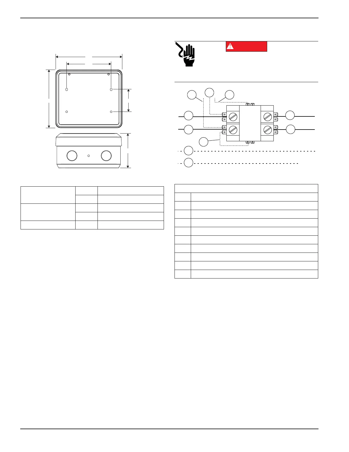
4. Hold SMM enclosure against mounting surface
with arrows (B) pointing up, and mark or drill four
mounting holes (C). See Figure 3-2 for mounting
dimensions if necessary.
Figure 3-2. Mounting Dimensions
5. Install SMM enclosure to mounting surface using
appropriate mounting screws or wall anchors.
Connections
Figure 3-3. Wiring Diagram
1. Turn off both UTILITY (NORMAL) and EMER-
GENCY (STANDBY) power supplies before con-
necting power source and load lines to transfer
switch and SMM.
NOTE: Suitable conduit fittings must be installed in
knockout openings when running supply and load wires.
Height (in/mm)
H1 6.17 / 156.8
H2 2.36 / 60
Width (in/mm)
W1 7.06 / 179.4
W2 4.72 / 120
Depth (in/mm) D1 3.7 / 94
Legend
A Red (240 VAC - Line)
B Black (240 VAC - Line)
C Red (240 VAC - Load)
D Black (240 VAC - Load)
E White - Neutral (as required)
F Green - Ground (as required)
G Black - Factory (PCB)
H Red - Factory (PCB)
I Blue - Factory (PCB)
J Blue - Factory (Jumper)
Electrocution. Turn utility and emergency
power supplies to OFF before connecting
power source and load lines. Failure to do so
will result in death or serious injury.
(000116)
DANGER
 Loading...