Installation, Tests, & Troubleshooting
Owner’s/Installation Manual for SMM 11
NOTE: Use at least 167 °F (75 °C) rated wire and gauge
per installation instructions. See Table 3-1 for recom-
mended wire size based on load current.
2. Run line supply wires per applicable NEC code
articles for wiring method selected.
3. Run load wires per applicable NEC code articles
for wiring method selected.
4. See Figure 3-3. Connect line supply wiring (A, B)
to line side of SMM contactor field terminals.
Tighten field terminals to 25 in-lbs (2.8 Nm).
5. Connect load supply wiring (C, D) to load side of
SMM contactor field terminals.
NOTE: If neutral (E) and ground (F) wires are included,
connect inside SMM using a listed termination device.
The unit is now ready to configure, apply power, and
perform testing.
Setting Priorities
High priority 240 VAC loads should be set to the highest
priorities so those loads recover first in the event of
generator overload.
NOTE:
The highest priority, and first load to activate, is
Priority 1. The last load to activate is Priority 8.
Setting priority determines timing for three scenarios:
• Order in which loads recover
• Delay time until power returns during an outage
• Delay time for post load shed recovery
An example configuration is shown below. Configurations
will vary depending on customer prioritization of loads:
1. Set the priority of each SMM as desired (using the
example configuration for reference).
2. Apply priority decal in a suitable location on electri-
cal panel to record chosen priority designations.
3. Record priorities on decal.
Tests
Utility Test
1. Turn utility power ON and enable all module feed-
ing circuits.
2. Verify LED begins to flash at one second intervals.
3. All contactors will close after five minutes. LED will
illuminate and remain ON.
NOTE: The five minute delay allows magnetism to dissi-
pate from the air conditioner compressor. This allows
easier starting and eliminates potential for reverse com-
pressor operation.
Installation Summary
•
Install cover on electrical panel.
• Install covers on modules.
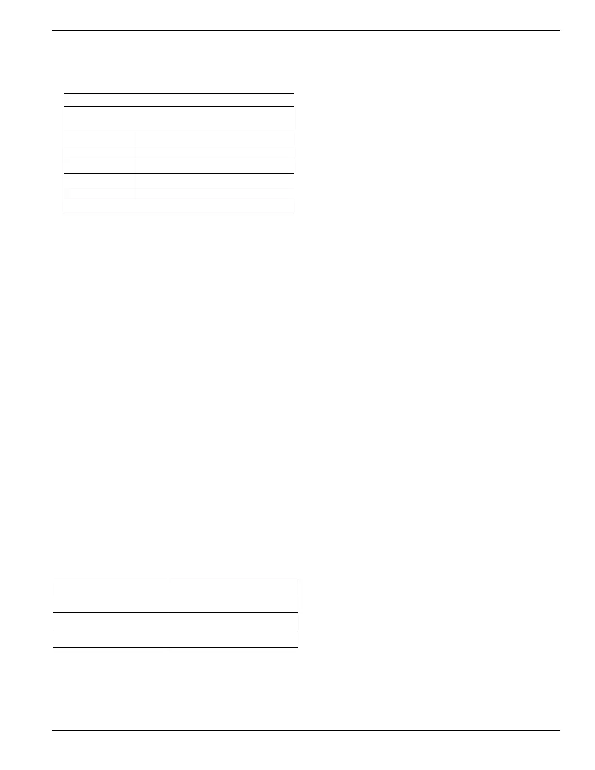
Table 3-1. Recommended Wire Sizes
Temperature rating of conductor: 167 ºF (75 ºC)
Conductor types (must be copper):
RHW, THHW, THW, THWN, XHHW, USE, ZW
Size AWG Maximum Current Rating
14 15A
12 20A
10 30A
8 50A*
* 40A for Type NM cable
Priority 1 - Baseboard heat Priority 5 - Non-essential circuits
Priority 2 - Air conditioner Priority 6 - Pool pump or hot tub
Priority 3 - Range Priority 7 - Other circuits
Priority 4 - Clothes Dryer Priority 8 - Other circuits
 Loading...